MECH4620 Group and Individual Project Aerodynamic Efficiency of Airfoils
Hello, dear friend, you can consult us at any time if you have any questions, add WeChat: daixieit
MECH4620 Group and Individual Project
Aerodynamic Efficiency of Airfoils
Problem Description
Reducing aircraft fuel consumption is a major global issue due to the growing concerns over the environment and the effects of global warming. Since fuel efficiency of an aircraft is significantly affected by the aerodynamic lift and drag, research on lift and drag performances, which enhances fuel efficiency, thus represents a significant environmental concern. Due to the rapid advancement of numerical methodologies and computational power, the application of computational fluid dynamics (CFD) has become a very cost-effective way to analyse the flow region around an aircraft. Most of its components, such as the wings, stabilisers, flaps, ailerons, and other high-lift devices, use different airfoil to optimise its performance and stability.
In this project, you will be considering the lift and drag over a NACA-0012, a symmetrical airfoil that has a maximum thickness at 12% of the chord from the leading edge, which is often used in aerodynamic analysis. This is a standard geometry employed as a benchmark for researchers to understand the flow around an airfoil and how their aerodynamic performance varies with design changes. A diagram of the NACA-0012 is shown in Fig. 1.
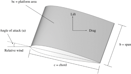
Fig. 1. NACA-0012 with dimensions shown [1].
Your model should have a chord length= 100 mm, thickness = 12 mm and span = 100 mm.
Your task is to investigate the lift and drag coefficients (Cl and Cd, respectively) of a NACA-0012 at different angles of attack (α), as well as the general flow characteristics around the body. In the experiment, the body was placed in a wind tunnel (L × H × W = 5 m × 2.3 m × 0.1 m) with a free-stream velocity of 45 m/s. According to experiment [2] and calculation, the resulting lift and drag coefficients are:
|
Angle of Attack (α, deg) |
Lift Coefficient, Cl |
Drag Coefficient, Cd |
|
0 |
0 |
0.00746 |
|
0.5 |
0.0513 |
0.00753 |
|
1 |
0.1053 |
0.00776 |
|
1.5 |
0.165 |
0.0081 |
|
2 |
0.2342 |
0.00852 |
|
2.5 |
0.3879 |
0.00943 |
|
3 |
0.4671 |
0.00992 |
|
3.5 |
0.5391 |
0.01042 |
|
4 |
0.584 |
0.01091 |
|
4.5 |
0.6271 |
0.01154 |
|
5 |
0.6686 |
0.01232 |
|
5.5 |
0.709 |
0.01319 |
|
6 |
0.7487 |
0.01413 |
|
6.5 |
0.7882 |
0.01511 |
|
7 |
0.8272 |
0.01619 |
|
7.5 |
0.8651 |
0.01743 |
|
8 |
0.9019 |
0.01891 |
|
8.5 |
0.9428 |
0.02005 |
|
9 |
0.9797 |
0.02188 |
|
9.5 |
1.0183 |
0.02335 |
|
10 |
1.0532 |
0.02567 |
|
10.5 |
1.0879 |
0.02755 |
|
11 |
1.1185 |
0.0304 |
|
11.5 |
1.1412 |
0.03292 |
|
12 |
1.1554 |
0.03576 |
|
12.5 |
1.1677 |
0.03882 |
|
13 |
1.1704 |
0.04388 |
|
13.5 |
1.1514 |
0.0498 |
|
14 |
1.1236 |
0.05844 |
|
15 |
1.083 |
0.07071 |
You should conduct CFD studies on NACA-0012 with respect to different angles of attack (ranging from 0 º - 15 º), you are advised to study at least 3 different angles.
Individual Assignment
You need to investigate the effect of multiple airfoil configuration installed on a multiplane (aircraft with multiple wings). The inter-distance and location of the wings can significantly alter the flow over the body and to affect the coefficients mentioned above.
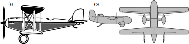
Fig. 2. Example of (a) Stacked multiplanes and (b) Tandem multiplanes
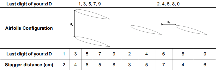
As demonstrated in Fig. 2, the configuration of the wings can be stacked one above the other (Biplane) or one behind the other (Tandem). Depending on your student zID, you will be investigating either the stacked multiplanes or tandem multiplanes, as seen in Table 2. The stagger distance between airfoils is also provided.
Table 2. Airfoil configuration based on Last digit of your student ID.
Group Assignment Tasks:
a) Generate the geometry with appropriate simplifications (e.g. symmetry) to represent the airfoil. Justify your assumptions and simplifications.
b) Generate an appropriate mesh for the geometry. Apply mesh refinement functions where necessary within the geometry.
c) Conduct a mesh sensitivity study to verify the model you have constructed.
d) Conduct CFD simulations by:
(i) Setting up your CFD simulation according to the configuration as shown in Fig. 1 with an inlet velocity of 45 m/s.
e) Choose and compare CFD sub-models (e.g. turbulence, boundary conditions).
f) Compare your numerical lift or drag coefficient with the experimental results provided in the previous section or from other online databases. It is OK if your results do not match the experimental results exactly. However, you must analyse the differences and explain the potential sources of error. Discuss the flow distribution and the drag and lift force on the Ahmed body observed from your simulation.
Individual Assignment Tasks:
Based on the computational model created in your group project, in your individual assignment you are asked to:
a) Obtain solutions of the NACA-0012 using two or more different discretisation schemes. Explain the scheme. Are the results as you expected? Which scheme do you recommend for this problem?
b) Investigate different airfoil configuration according to your student zID with at least 3 angle of attack. Just ONE stagger distance corresponding to your zID.
c) Discuss how the airfoils’ configuration and their stagger distance affects the flow distribution and the drag and lift force on the system. In-depth discussions are desired, not just shallow descriptions. Provide various CFD data to support your discussion.
d) Redesign the airfoil configuration to optimise the aerodynamics performance. You shall focus on minimising the drag and maximising lift coefficient (maximise lift-to-drag ratio). Excessive drag will affect the speed and fuel efficiency, while a high lift will enhance the aircrafts' aerodynamic efficiency. (Hint: you can start by modifying the configurations of the airfoils). Please note that the stagger distance between the airfoil should not exceed 15 cm.
2025-04-26