ME 270 – Fall 2015 Final Exam
Hello, dear friend, you can consult us at any time if you have any questions, add WeChat: daixieit
ME 270 – Fall 2015 Final Exam
PROBLEM 1.
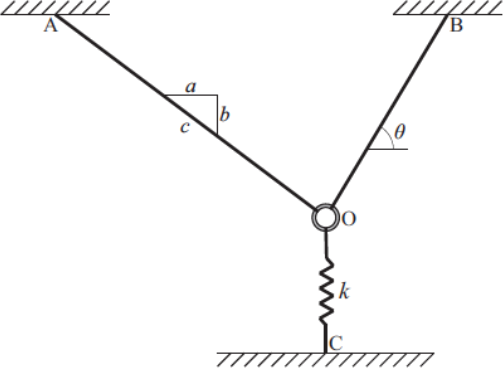
1a. Equilbrium. The ring is held in equilibrium by two cables and a spring. At equilibrium the spring is stretched 0.15 m and the spring constant, k = 1,000 N/m. In order to maintain equilibrium, the cable OB makes an angle, θ = 60o and a, b, c makes a 4, 3, 5 triangle. Draw a free body diagram and determine the forces in the two cables. (7 points)
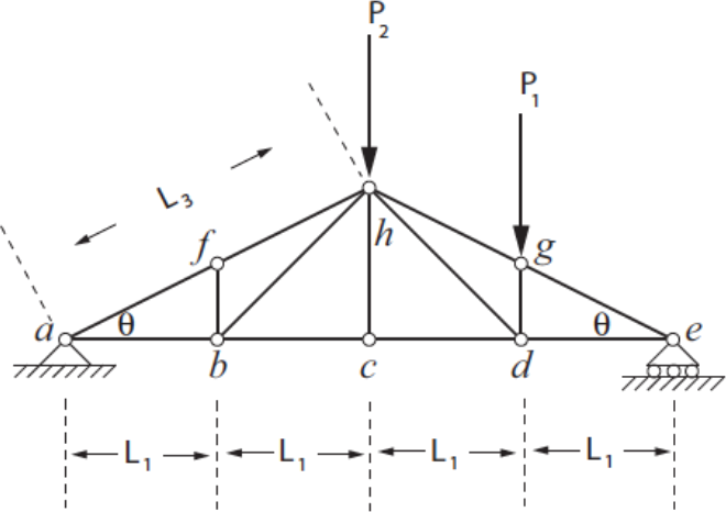
1b. Find the zero force members. Place a “0” on each zero force member in the truss below. (4points)
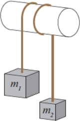
1c. Friction: If m1 = 100 kg and μ = 0.35, what is the range of masses for m2 that will keep the system in equilibrium? (4 points)
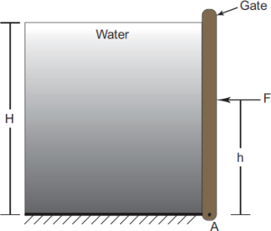
1d. Fluids: If H = 10 m, h = 3 m, the gate extends 1 m into the page, and the density of the water is 1,000 kg/m3, determine the force, F, required to hold the gate in place. (5 points)
PROBLEM 2. (20 points)
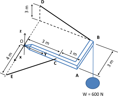
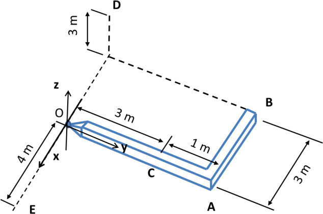
GIVEN: A L-shaped beam, OAB, (ignore its weight) is supported at O with a ball joint, a weight of 600 N (acting in the negative z direction) is attached at B, and two cables BD and CE are used to connect the beam to the wall. Use the dimensions as shown in the left figure.
FIND:
a) Complete the free body diagram in the provided figure below (4 pts).
b) Express the tensions in the cables in terms of their unit vector and unknown magnitude (4 pts).
|
T(̅)BD = T(̅)CE = |
(4 pts) |
c) Determine the magnitudes of the tensions in each cable (6 pts).
|
TBD = TCE = |
(6 pts) |
d) Determine the reaction forces at the ball joint O and express it in the vector form (6 pts).
Reaction force at O: (6 pts)
![]()
PROBLEM 3. (20 points)
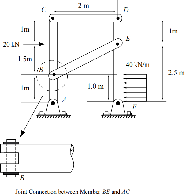
GIVEN: Shown below is a frame of negligible weight that is pinned at A and F. A 20 kN force is
applied to member AC of the frame and a rectangular distributed load with intensity of 40 kN//m is applied to member DF.
FIND:
a) Circle the two force members (1 points): AC, CD, BE, DF
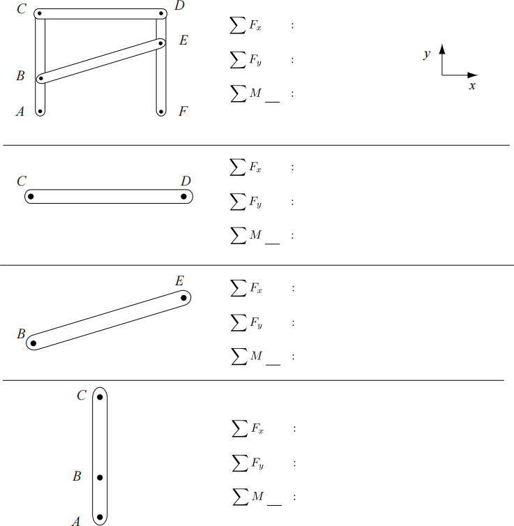
b) (10 points) Draw the FBD of the frame/ and member below. Fill in the blanks for the summation of forces and moments. Indicate in the blank behind the summation of moment expression the point that you are taking the moments about. In the FBD’s be sure to reduce any distributed load to an equivalent force and given the appropriate location. If the member is a two-force member leave the moment expression blank.
c) (5 points) The force carried by member BE is kN. What is the sign of the force + or - (circle one) .You may use the space below for your work.
d) ( 2 points ) Pin B has a diameter of 1 mm. Calculate the shear stress on pin B ,
tB = Pa. You may use the space below for your work.
e) ( 2 points ) If member BE is made of Aluminum (E = 73 x 109 Pa and σy= 410 x 106 Pa) and its
cross section is square. Using a factor of safety of 2, the width/height of the beam is
m to prevent failure from yielding. You may use the space below for your work.
PROBLEM 4
4a. Given the shear-force and bending-moment diagrams provided below, sketch the equivalent
loading condition on the beam provided below. Make sure you indicate both the magnitude and the direction of each load. (5 pts)
PROBLEM 4 (cont.)
4b. A hollow shaft with an external diameter of 150 mm is required to provide a torque of 12 kN-m. The yield shear stress of the material is 140 MN/m2. Assuming a safety factor (FS) of 2, calculate
(i) the maximum allowable shear stress τmax, and
(ii) a suitable internal diameter (di) of the shaft if the shear stress is not to exceed this allowable
shear stress. (Hint: Write down the polar moment of the shaft in terms of the internal diameter).
|
τmax = MN/m2 (2 pts) di = mm (3 pts) |
4c. A beam has a constant L-shaped cross section shown in the diagram. Find the location of the centroid yc from the x-axis. Determine the second moment of area IG corresponding to the neutral axis of the beam.
|
yc = in (2 pts) IG = in4 (3 pts) |
4d. Determine the second moment area of the shaded region about the x-axis, Ix by integration. Then, use the parallel axis theorem to calculate the second moment area, IH about the axis H-H at y = 6. For the shaded region, you may take its area as 12 and the location of the centroid (measured from the x-axis) as 4.571, respectively. (Hint: the axis H-H does not pass through the neutral axis of the shaded region.)
|
Ix = (3 pts) IH = (2 pts) |
2024-08-02