BIOB32 LABORATORY EXPERIMENT #6
Hello, dear friend, you can consult us at any time if you have any questions, add WeChat: daixieit
BIOB32 LABORATORY EXPERIMENT #6
EFFECT OF TEMPERATURE ON THE CONDUCTION VELOCITY AND ABSOLUTE REFRACTORY PERIOD DURATION OF COMPOUND ACTION POTENTIALS OF A CRAB NERVE
BACKGROUND INFORMATION AND OBJECTIVES:
Measuring action potentials:
Intracellular action potential recordings allow us to examine the behaviour of single excitable cells (e.g., single neurons or muscle fibers); however, intracellular recordings are technically quite difficult and rely on equipment that is not available for use in this laboratory session. Extracellular recordings of the action potentials from single cells, like those you obtained last week, are possible, but only in situations where the cell in question is large and spatially separated from other cells (e.g., the earthworm nerve cord). In most multicellular animals, multiple neurons, and the axons and dendrites from those neurons, are typically found in close association. In particular, most nerves in our body, and the bodies of other larger animals, are composed of dozens or hundreds of axons each.
In this laboratory session, you will examine the propagation of signals along a large nerve, composed of many unmyelinated axons, from a crab leg. This signal, termed a compound action potential (CAP), shares some features in common with a single action potential, but also exhibits some features that are different. Like a single action potential, there is a minimum threshold stimulation intensity below which no CAP will be elicited; however, unlike in a single action potential, the amplitude of the CAP can change as stimulation intensity is increased further. This is because the CAP is made up of the roughly synchronous firing of multiple axons within the nerve. While each individual action potential is “all-or-none”, the firing of more or fewer of the axons within the nerve will lead to a CAP with a larger or smaller relative amplitude, respectively. The conduction velocity of individual action potentials along separate axons may vary because, for example, some axons may be larger in diameter than others; however, the average conduction velocity of the population of axons along which action potentials are propagating can be measured. This is the conduction velocity of the CAP.
Nerve refractoriness:
The neuronal membrane becomes briefly refractory following each firing of an action potential. There are two different types of refractory period: absolute and relative. In the absolute refractory period, an axon will not fire again even if it is stimulated with a suprathreshold stimulus. In the relative refractory period, an axon will fire again, but only if it is stimulated with a suprathreshold stimulus, and the amplitude of the action potential will be reduced.
Since the CAP is an emergent phenomenon resulting from the firing of many individual axons, it follows that a whole nerve exhibits a period of refractoriness as well—both absolute and relative. You will observe this refractoriness by delivering multiple stimulation pulses in succession, increasing the stimulation frequency (and thus decreasing the delay between stimulus pulses) until you no longer observe a CAP for each stimulation pulse.
To understand why a section of excitable membrane can become refractory, we must think about what is going on with the actual ion channels that are responsible for the phenomenon of the action potential. The rising phase of the action potential is caused, in typical excitable cells, by the opening of large numbers of individual voltage-gated Na+ channels. Na+ experiences rapid net flux down its electrochemical gradient into the cell, causing the membrane potential (Vm) to rise (Figure 1). Vm peaks and begins to fall for two reasons: 1) voltage-gated K+ channels, which are triggered at the same time as the Na+ channels, but are slower to respond, open in large numbers, permitting the flow of K+ ions out of the cell, causing Vm repolarization; this can offset inward flux of positive current from a new stimulus, and in this way, contribute to the relative inability of this portion of the membrane to initiate a new AP, leading to the relative refractory period; and 2) voltage-gated Na+ channels stop permitting the flow of Na+ as their inactivating particles swing into an inactive position. The inactivating particles remain in place until membrane repolarization back below threshold potential occurs, and during this time, the channels cannot open again. The action of the inactivating particle in making voltage-gated Na+ channels temporarily unresponsive to new activation leads to the absolute refractory period.
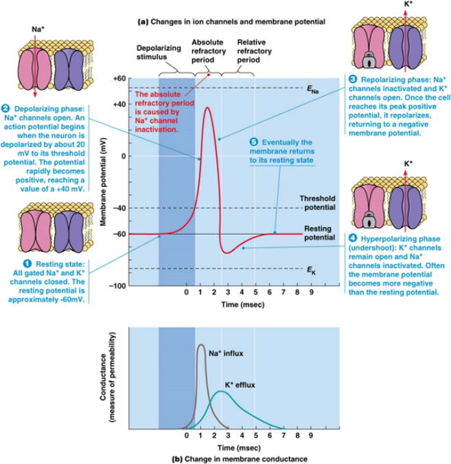
Figure 1. Properties of an action potential and the voltage-gated channels that underlie them.
LINK FOR DATA SHEETS FOR DATA ENTRY (FOR THIS LAB YOU WILL USE CLASS DATA):
LABORATORY PROCEDURE:
NOTES:
● Electrophysiology cables are very delicate. Always handle (attach, detach, etc.) cables by holding the plug itself. Never yank on the cord. Do not take cables from other benches.
● If you have exhausted troubleshooting options and believe you have a damaged cable, please alert the TA or technician.
● Please keep in mind, cables are all tested ahead of time. It is very unlikely that you have a damaged cable.
● Set the BSLSTM Stimulator on the bench next to the MP36 unit (separated by several inches). Do not place the stimulator on top of the MP36, as this may introduce unwanted noise.
● Do not touch the crab’s nerves with any metallic tools. Doing so may damage the nerves, rendering them useless for this experiment.
PART I: EQUIPMENT SETUP
Hardware Setup
1. Connect the Stimulator to the MP36 (consult Figures 2 and 3):
● Connect the “BSLSTMB Trigger” cable from the BSLSTMB to the “Analog Out” port on the back of the MP36.
● Connect the “BSLSTMB Reference Output” cable from the BSLSTMB TO “CH 2” on the front of the MP36.
2. Connect the “BSLCBL1A” cable from the “Output” connector on the front of the BSLSTM
unit to the NERVE CHAMBER.
3. Connect the “BSLCBL3A” recording cable from “CH 1” on the MP36 to the NERVE
CHAMBER.
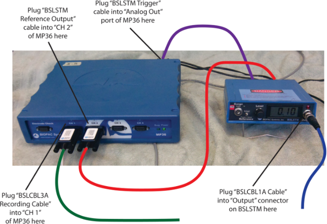
Figure 2.
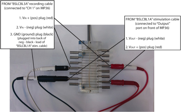
Figure 3.
Software Setup
1. Make sure MP36 is connected to Dell Laptop and that it is powered ON.
2. Click on Biopac Student Lab 4.1 icon on desktop
3. Select: Create/Record a new experiment (yellow box)
4. Select: Open graph template from disk (grey box). Click OK.
5. Double Click on: This PC
6. Scroll down. Open: Local Disk C
7. Open Biopac BSL 4.0
8. Open: Template Biopac Files
9. Open: Lab 8 Crab Leg Nerve.gtl.
To save your work: Create a folder on desktop (it will automatically be deleted once you sign out). You MUST rename your file (do not save “untitled”) ie. Prac # and group name. Your file will be saved as .acq file.
PART II: THE CRAB MERUS NERVE
Background
A 5 to 6 cm length of nerve removed from the merus segment of a crab walking leg (see Figure 4) will be provided in crab Ringer’s solution (see Figure 5). Clean the NERVE CHAMBER at the sink and prepare your station.
A thread will be tied around one end of the nerve to aid in transferring the nerve to the chamber. Keep in mind that this nerve is very delicate and must be handled carefully. Throughout the procedure, pipette room temperature crab Ringer’s solution onto the nerve. Measure the temperature of this crab Ringer’s solution and record this value in the Data Sheets.
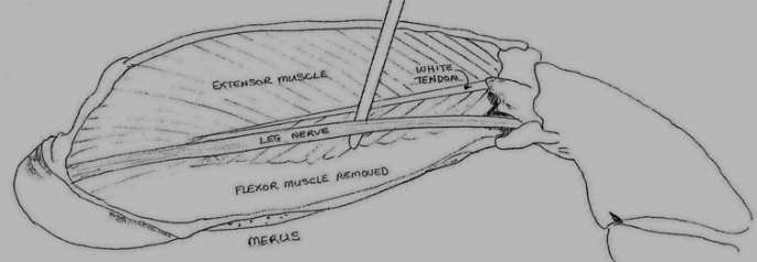
Figure 4. Diagram showing the location of the nerve to be used in this laboratory experiment.
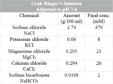
Figure 5.
PART III: THRESHOLD AND MAXIMUM STIMULATION INTENSITY
1. Make sure the “Pulse Duration Setting” is set to 0.8 ms and the “Pulse Number Setting”
is set to 1 (see Figure 6).
2. Set the BSLSTM stimulator to 0.0 V by adjusting the front dial.
3. Click the “Start” button to record.
• Remember to take detailed notes along the way.
4. Adjust the stimulation intensity to 0.1 V
5. Click the “Start” button to record.
6. Continue, increasing the voltage in a stepwise fashion until you observe a CAP.
7. Note the stimulus intensity at which this CAP was first elicited.
• This is the “threshold voltage” for the crab nerve. Record this value.
8. In addition, note the amplitude of the CAP that results.
• Use the Cursor Selection Tool to highlight the peak of the CAP.
• Read the “Max” value calculation value (Fig. 5, located just above and to the left of the
“Start” button).
• Record this value.
9. Continue, increasing voltage as before, by 0.1 V increments.
• Note the amplitude of the CAP, as above.
10. Eventually, you will reach a stimulus intensity above which the amplitude of the resulting
CAP no longer increases.
11. This is the maximal stimulation intensity.
• Record this value.
12. Save your data with an appropriate file name, use your cursor to select the entire
recording area, and click EDIT>CLEAR ALL.
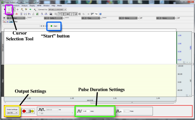
Figure 6. Screenshot of the BSL Pro 4.0 window highlighting several important tools. Note that the “Pulse Frequency Setting” is directly to the left of the “Pulse Duration Setting”. The “Pulse Number Setting” is directly to the right of these.
PART IV: MEASURING THE CONDUCTION VELOCITY OF THE CRAB NERVE
1. Note the position of the electrodes attached to your NERVE CHAMBER.
• Measure the distance (in mm) between VOUT + (pos) and VIN + (pos). Record this
value (d1).
2. Set the BSLSTM stimulator to the threshold voltage that elicited a CAP from the nerve.
3. Click the “Start” button to record.
• Remember to take detailed notes along the way.
4. Use the cursor tool to highlight the time period between the leading edge of the
stimulation pulse and the peak of the CAP. Record this value (t1).
5. Move the recording electrodes VIN + (pos) and VIN - (neg) further away from the
stimulating electrodes. Note the distance (in mm) between recording and stimulating
electrodes. Record this value (d2).
6. Click the “Start” button to record.
7. Use the cursor tool to highlight the time period between the leading edge of the
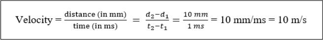
stimulation pulse and the peak of the CAP. Record this value (t2).
8. Calculate room temperature conduction velocity using the equation below.
PART V: NERVE REFRACTORY PERIOD
Background
Recall what is written in the introduction section at the beginning of this lab manual. Nerve refractoriness is due to two factors: a) the action of the inactivating particle in making voltage-gated Na+ channels temporarily unresponsive to new activation, and b) the repolarization/after-hyperpolarization due to high permeability of the membrane to K+ efflux. Both phenomena explain why a given section of membrane cannot be made to fire a new action potential, no matter how much stimulation is applied.
You will apply two stimulation pulses in rapid succession, decreasing the period of time between the subsequent stimulations, until you are no longer able to successfully trigger two CAPs. In doing so, you will demonstrate nerve refractoriness.
Examine Nerve Refractoriness
NOTE: Make sure you can see the RAW (unfiltered) recording trace. The CAPs are easier to see here when delivering two pulses as the first CAP might be occurring close to the time of the second stimulus delivery.
1. Make sure the “Stimulation Duration Setting” is set to 0.8 ms, the “Pulse Number
Setting” is set to 2, and the “Pulse Frequency Setting” is set to 1 Hz. (see Figure 6).
1Hz = 1 pulse per second, which is also 1000ms between pulses.
• To change the “Pulse Number Setting”, right-click on the window with Pulse; go to
Preferences, Select “multiple”, Choose 2, click OK.
2. Set the BSLSTM stimulator to the maximum stimulation intensity you determined
previously.
3. Hit the “Start” button.
• You should observe 2 CAPs, one coming after each of the stimulation pulses.
4. Increase the “Pulse Frequency Setting” to 100 Hz (see Figure 6). 100Hz = 100 pulses
per second, which is also 10ms between pulses.
5. Repeat steps 3 and 4 above, increasing the stimulation frequency until you no longer
observe the second CAP.
• You can increase frequency by 100 Hz increments as you will likely need to get to a fairly
high value (in the 500-750 Hz range).
7. If you reach a “Pulse Frequency Setting” value above 1000 Hz with no luck, increase the
stimulation voltage by 0.5 V increments and repeat.
8. Once you have determined the “Pulse Frequency Setting” at which a second CAP no longer occurs, determine absolute refractory period as follows:
Absolute Refractory Period (ms) = 
PART VI: EFFECT OF TEMPERATURE ON CONDUCTION VELOCITY AND ABSOLUTE REFRACTORY PERIOD
1. Place the nerve cord in a petri dish filled with chilled Ringer’s solution. Using a
thermometer, record the temperature and record this value in the Data Sheets.
2. After letting the prep cool for 20-30 seconds, quickly place it in the NERVE CHAMBER
again. Keep the prep cool by pipetting chilled Ringer’s solution regularly. Throughout the
procedure, pipette the nerve with chilled crab Ringer’s solution to keep the nerve cold.
3. Repeat Part IV and Part V above, which will allow you to determine how cold
temperature affects both CAP conduction velocity and absolute refractory period.
PART VII: CLEAN UP
● Leave all electrical cables at your lab bench (broken cables must be reported to the TA/technician)
● Leave all other equipment at your bench (i.e. scissors, pipette, beakers, thread, etc.)
● Return nerve to its original container
STATISTICAL ANALYSIS
1. For both conduction velocity and absolute refractory period, conduct a paired t-test between the values for the two temperatures in order to determine whether temperature had any significant effect on either of these parameters.
2. In the Data Sheets, the Q10 value for both conduction velocity and absolute refractory period will be automatically calculated. You should report these values in your lab assignment, where appropriate.
2024-03-29
EFFECT OF TEMPERATURE ON THE CONDUCTION VELOCITY AND ABSOLUTE REFRACTORY PERIOD DURATION OF COMPOUND ACTION POTENTIALS OF A CRAB NERVE