ELEC7310, MODULE I: POWER SYSTEM STABILITY AND DYNAMICS Assignment # 3
Hello, dear friend, you can consult us at any time if you have any questions, add WeChat: daixieit
ELEC7310, MODULE I: POWER SYSTEM STABILITY AND DYNAMICS
(SECURITY)
Assignment # 3: Small Signal Stability
Submission Date: April 19, 2024
Use any analytical software tools (PSAT, PSS/E, DSA Tool, or PST are preferred) to study the small signal stability of the following test system.
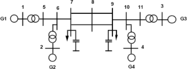
Fig. 1. A single-line diagram of two-area test system.
The Fig.1 shows a single-line diagram of two-area power system, typically used for power system low frequency (small signal stability) oscillation studies. The system consists of eleven nodes, including four generators with step-up transformers and two loads, and thirteen branches.
The basic data of the test system for both static and dynamic analysis can be obtained from the example 12.6 of reference [1].
In PSAT the two-area test system can be obtained by modifying the “d_kundur1” Simulink file given in “tests” folder. The required modifications include removing the ZIP loads and the fault.
Carry out Eigen value analysis and comment on the system stability status for the steps (a) to (g). Identify different modes of oscillations and justify your answers by considering frequency of oscillations and participation factors.
(a) Model all the generators as classical models to study the small signal performance of the system and report on the obtained results.
(b) Model all the generators in detail; all the generators have identical parameters, calculate the eigenvalues of the system at the base case and 20% increased loading level.
(c) Introduce different exciters in each of those generators and repeat the eigenvalue calculation.
(d) Introduce governor models and repeat the calculation again.
(e) Using the participation factor analysis, find out what are the state variables dominant in the critical mode and the corresponding machine (problematic one).
(f) Introduce a Power System Stabilizer (PSS) in the problematic machine and calculate the eigenvalues again.
(g) Repeat the calculation with PSS in all four machines of the system.
(h) Draw the time-domain responses of generator rotor angles and tie-line power flow to justify your obtained results in (f) and (g).
Students are requested to present all the relevant results in tables and/or graphs. It is also expected from the students to make appropriate comments on each step of this analysis.
Total mark: 8
[1] P. Kundur, Power System Stability and Control: McGraw-Hill, 1994.
2024-03-14
Small Signal Stability