Mechatronics 5CCE2MCT Individual Coursework Project
Hello, dear friend, you can consult us at any time if you have any questions, add WeChat: daixieit
Mechatronics 5CCE2MCT Individual Coursework Project
Design Analysis of a Two-aris Camera Gantry System
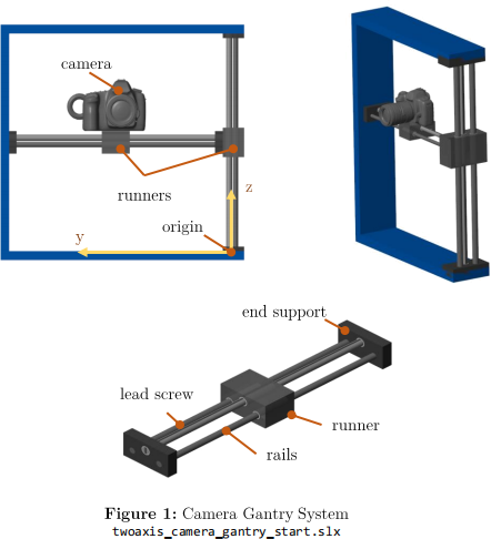
You are a mechatronics design engineer working for a firm that specialises in developing custom components for cinematic production.Your manager has sent you a parametric model of a two- axis gantry mechanism that was developed on a previous project.The gantry can move a camera both horizontally and vertically by rotating lead screw mechanisms attached to runners.
Brief
Your manager has asked you to design a new electromechanical actuation system composed of two geared DC motors that drive the leadscrew runners of the two-axis gantry system shown in Figure 1.She provided CAD components and Simulink starter models for the assembly,n.b. these files can be downloaded from the KEATS module page in the MATLAB project archive, camera_gantry.mlproj.She has also sent you a list of requirements that she has discussed with the customer appended to the end of this document.She encourages you to use the model as a starting point and welcomes further input on how to improve the mechanical design.
You are responsible for:
· specifying DC motor,power supply,and gearbox characteristics
· design a digital motor controller
· demonstrate the effectiveness of your design.
You are highly encouraged to brainstorm additional information about the context in which this mechanical system is to be used.
Deliverables
· a 3-minute video recording in which you present the motor and mechanism design to an engineering design team.The video should contain an animation of the mechanism and an overview of the Simulink model and results.
· a l-page written report presenting the results of your design analysis with a maximum of 2 page of supporting figures in appendix
· zip and upload Simulink model to KEATs
Learning objectives
· Model the electromechanical system that actuates the gantry using a combination of mathematical,physical and data-driven methods and critique the choice of your modelling approach
· Specify component parameters based on a design analysis of system requirements · Implement and tune a feedback controller to control position and speed of the mechanism
· Test the controller design against multiple loading scenarios
· Conduct a design space study to optimise system-level performance
· Report and justify recommended design implementation
Additional resources
You are encouraged to complete laboratory exercises of weeks 22-26 to develop skills in modelling and control of mechatronics systems.
|
Marking Criteria Individual coursework submission accounts for 30%of module grade. Your submission will be scored with regards to its merits in six core areas: |
|
|
Area |
Actions Justify modelling and control design approach |
|
Science & |
|
|
Mathematics |
Interpret design performance using mathematical and statistical techniques |
|
(20 marks) |
Critique choice for actuator and sensor characteristics and technology |
|
Engineering |
Apply engineering tools to solve the design task |
|
Analysis |
Conduct critical analysis to identify,classify and describe system performance |
|
(20 marks) |
compared to benchmark Adopt systems approach to improve on design Extract and evaluate pertinent data to solve unfamiliar problems |
|
Engineering |
Evaluate user needs and requirements |
|
Design |
Identify and work with design constraints and unknowns |
|
(20 marks) |
Communicate to a technical audience Deliver efficient,effective and robust design |
Engineering Context
(10 marks)
Identify and mitigate areas of risk
|
Engineering Demonstrate design effectiveness in the context in which the system is applied |
|
Practice |
|
(20 marks) |
|
Additional Demonstrate effectiveness,clarity and originality of communication |
|
General |
|
skills |
|
(10 marks) |
Requirements
Your manager discussed these requirements with the customer.You are welcome to add you own requirements to this initial draft.
Battery /Power Supply Requirements
Battery Voltage:5-12V
Battery Capacity:2-5 Ah
Battery Resistance:0.1-1 Ω
Battery Lifespan:15-20 minutes
You can use 18650 Li-lon batteries (example'
Battery Voltage:3.7V per battery*
Battery Capacity:2.6 Ah
Battery Resistance:250 m2 per battery
*n.b.1 battery is 3.7V(1S),2 batteries is 7.4V(2S),3 batteries is 11.1V (3S)and so on.
Lead Screw
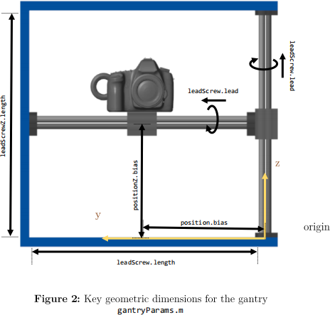
Linear travel per revolution of the screw 5-20 mm**
**n.b.parameter saved as leadScrew.lead =10; in the gantryParams.m script
DC Motor Requirements
Stall current:0.2A-1A
Stall torque:500 g.cm
No-load speed:7000-21000 rpm
Motor Sensor Requirements
Hall Sensor Encoder with 24 counts per revolution
Gantry Lift Requirements
Lift a camera payload weight of 10-20 kg
Camera Safety Requirements
No collisions with frame
Fail safe mechanisms for operation and calibration
Maximum acceleration of 30 m/s²
Camera Manipulation Requirements
Cover an area of 0.75 by 0.4 m²
Maximum jerk of 10 m/s3***
Suggestion: As the jerk is the derivative of the acceleration,this result is sensitive to the filtering of the acceleration signal. Use a first-order filter with time delay constant of 0.01 s when you take the derivative
System Response Requirements
Rise time<3-5 s per 100 mm travel
Settling time<5-7 s per 100 mm travel
Overshoot <2%
Undershoot<2%
Steady-state error<2%
Suggestion: Perform a step-response between the two ends of the frame.
Tracking Response Requirements
Relative error<3%
Absolute error <3%
![]() Suggestion: Perform a tracking-response using a sine wave or polynomial trajectory.
Suggestion: Perform a tracking-response using a sine wave or polynomial trajectory.
2024-02-29
Design Analysis of a Two-aris Camera Gantry System