CS 480 Computer Graphics Spring 2024 Assignment 2
Hello, dear friend, you can consult us at any time if you have any questions, add WeChat: daixieit
CS 480 Computer Graphics
Spring 2024
Assignment 2
Due Date: 02.27.2024, 11.59pm
In this assignment, there are 2 sections. The first section is the description and requirements for the deliverable, and the second section consists of the instructional tutorials. We recommend reading through the description of deliverables first, then follow the instructional tutorials for more context.
Deliverables
PART 1) Write an .obj file for a cube and import it into Blender.
To gain a practical understanding of .obj files, you'll create one by yourself. Follow these steps:
1. Open the initial file provided named `myCube.obj` in your chosen text editor.
2. Observe the file content. Populate the file with the required vertex and face information to model a cube of 1 unit side length, with one vertex at the origin (0, 0, 0). You can modify or remove the sample lines provided in the .obj file as necessary.
3. In Blender, start a new project, remove the default cube, and import your custom .obj file to verify that your cube displays correctly with all vertices and faces.
What to submit:
- Your .obj file and the screenshot of the cube within Blender.
1.1 Apply geometric transformation to an object.
To understand geometric transformations(translating, rotating, and scaling points in a coordinate space), follow these steps below:
1. Open the starter file provided named `myTransformation.blend`, which should load into the scripting tab with initial code ready. Read through the code.
2. Implement functions to generate the appropriate translation matrix for a given translation vector and axis, and rotation matrix for a specified rotation degree and axis.
3. Activate the previously commented code lines to apply the following transformations to four separate cones:
(a) Rotate around the x-axis by 45 degrees, then around the y-axis by 45 degrees.
(b) Rotate around the y-axis by 45 degrees, then around the x-axis by 45 degrees.
(c) Translate along the x-axis by 10 units, then rotate around the y-axis by 45 degrees.
(d) Rotate around the y-axis by 45 degrees, then translate along the x-axis by 10 units.
4. In a new Blender project, create a scene, remove the default cube, and add a cone. Manually apply the four transformation configurations mentioned in step 3 using Blender's translation and rotation shortcuts to replicate the outcomes of step 3.
What to submit:
- 4 screenshots that show 3D viewport and the script tab with your modification for 4 configurations mentioned in step 3.
- 4 screenshots that show 3D viewport and the Blender GUI(Property Editor) of your new Blender project for 4 configurations mentioned in step 3.
- Note, the result of your script should match the results of your Blender GUI transformations.
1.2 Model a unique piece of geometry in Blender.
In this part of the assignment, the Blender’s modeling capabilities is explored. The goal is to experiment with one or two modeling techniques that interest you, potentially aiding in the development of objects for your final project. The assignment is designed to be flexible, allowing for the creation of objects ranging from simple to complex. Here are some suggested methods for editing geometry, from which you can select one or combine several:
- Edit Mode: Start with a basic shape and switch to Edit Mode to modify vertices, edges, and faces. This approach is akin to working with a CAD tool, ideal for those interested in engineering. It involves adding new points, creating connections, and manipulating the geometry's structure.
- Sculpt Mode: Begin with a basic shape and use Sculpt Mode to mold the mesh like clay. This method suits individuals with a passion for drawing or sculpting, as the mesh dynamically conforms to your input strokes.
- Geometry Nodes: Create a simple shape and then utilize Geometry Nodes to alter its form. This technique is perfect for those who enjoy coding or mathematics, as it employs node-based commands to procedurally generate and transform geometry.
This part of the assignment encourages you stepping out of your comfort zone to try something new. While specializing in a single technique can be beneficial, gaining familiarity with a broad range of tools will serve you well, especially as you progress towards your final project.
What to submit:
- A screenshot of any unique piece of geometry that you made in Blender. It should be more complex than a built-in shape.
PART 2) Tutorials & Additional Information
2.1 Blender and Command Line: Debugging Scripts
To conduct advanced Python development in Blender and enable debugging through the command line, follow these steps:
- Windows:
1) Press Windows + R on your keyboard to open the "Run" dialog.
2) Type `cmd` and press Enter to open the Command Prompt.
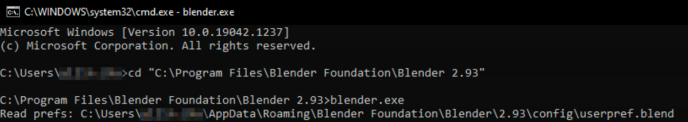
3) Change the directory to your Blender installation folder. For example: by typing cd C:\Program Files\Blender Foundation\Blender 3.5 and pressing Enter. Adjust the path if your Blender installation is in a different location.
4) In the Blender directory, type blender.exe and press Enter. This method allows Blender to output bugs or any other information that you print using the print() function directly to the command line.
- MacOS: Please refer to the official document linked here:
https://docs.blender.org/manual/en/3.3/advanced/command_line/launch/macos.html
- Linux: Please refer to the official document linked here:
https://docs.blender.org/manual/en/3.3/advanced/command_line/launch/linux.html
2.2 Dive into OBJ File Format in Detail
As discussed in lecture, one of the most used file formats to store graphics data is the Wavefront .obj format. To get an in depth view of how the file format works, let’s examine an .obj file. To look at the .obj file at a lower level, open the sphere example file, `sphere.obj`, in your favorite text editing program (e.g. Notepad++, TextEdit, Sublime Text, etc). Scrolling through the file, you may notice the following file structure:
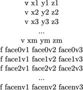
This example illustrates the simplest structure of the .obj file format, featuring a collection of vertex coordinates and triangular faces that define the shape of a 3D mesh. The positions of these vertices are given in the object's local coordinate system, as explained in the lecture.
- Vertices: Specified with the prefix v, followed by their x, y, and z coordinates in the object's local space. For instance, v 0.0 0.0 0.0 denotes a vertex at the origin.
- Faces: Defined with the prefix f, followed by the indices(integer) of the vertices that form each face. These indices reference the previously listed vertices. For triangular faces, you would see entries like f 1 8 37, indicating a face made by the first, eighths, and thirty-seventh vertices specified in the file. Note that du to convention, the vertices are 1-indexed.
Complex Obj Files: If you are curious enough and you try exporting the default cube as an .obj file and then examining it in a text editor, you will see a lot more data in the file than just the vertices and faces. We will discuss this other data later in the class. Meanwhile, you might find this website a good reference: https://paulbourke.net/dataformats/obj/
2.3 Transforming Objects in Blender
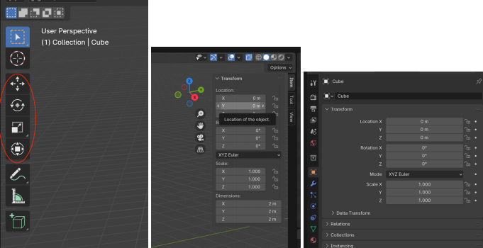
In Blender, you can manipulate an object using the Move, Rotate, Scale, and Transform tools found in the 3D viewport's left toolbar. When an object is selected using these tools, an orange dot (indicating the object's origin) and colored lines representing the axes for movement will appear. For quick adjustments, the keyboard shortcuts are 'G' (grab/translate), 'R' (rotate), and 'S' (scale). To constrain movements to a particular axis, you can follow these shortcuts with 'X', 'Y', or 'Z'. For instance, pressing 'G' then 'X' allows you to move the object exclusively along the X-axis. Inputting numerical values after these commands enables precise transformations, like moving an object 2 units on the Z-axis by pressing 'G', 'Z', 2, and then Enter.
Note: Ensure your cursor is within the 3D viewport when using these shortcuts to direct your inputs correctly.
Local Transformations:
In Blender, the local transform of an object can be observed and modified from two additional locations within the interface. The first is within the 3D viewport's sidebar, accessible by pressing 'N'. The second is found under the Object Properties section, identifiable by an orange square icon, located in the bottom right corner. Here, you can view and adjust the local position (translation), rotation, and scale of the selected object.
Rotating Objects about the Global World Origin:
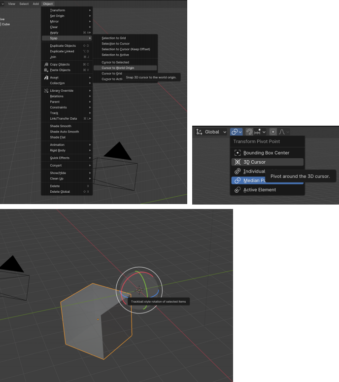
When you rotate an object in Blender using the tools mentioned earlier, it rotates around its own origin point instead of the world space origin. For example, if you move the default cube 5 units along the X-axis and then attempt to rotate it around the Z-axis, the cube will rotate around its own center rather than the global Z-axis. This behavior occurs because Blender, by default, performs local transformations based on the object's own origin.
To have an object rotate around the global axes in Blender, navigate to the Object dropdown menu located near the Object Mode indicator. If you are in Edit Mode, the option will be available under a different dropdown menu in the same location. From there, change the transform pivot setting, found next to the Global indicator, to "3D Cursor" in the dropdown menu. After setting this, using the rotate tool or the 'R' keyboard shortcut will result in the object rotating around the world origin.
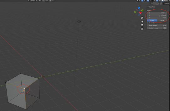
Viewing the Global Coordinates of a Vertex:
To view a vertex's coordinates in Blender, first enter Edit Mode and select a vertex. Then, press the 'N' keyboard shortcut to open the sidebar in the 3D viewport. By default, this sidebar shows the local coordinates of the vertex, which are relative to the object's origin. To view the vertex's global coordinates, which are relative to the global origin, toggle the display setting in the sidebar to "Global".
2.4 Modeling Geometry in Blender
Polygon Modeling
Polygon modeling is the foundation of all 3D modeling software, involving the manipulation of polygonal meshes through the adjustment of vertices, edges, and faces. This method is particularly suited for crafting hard-surface objects, such as man-made items with precise edges and angles, due to the control it offers over the positioning of individual vertices. However, for organic shapes or effects, sculpting is often a more appropriate technique, as polygon modeling may not capture the nuanced curves and natural forms as effectively.
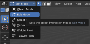
To access the modeling tools in Blender and make changes to objects at the vertex/edge/face- level, we will want to be in Edit Mode . Once in Edit Mode , you will notice that 1) new tools have appeared in the sidebar, and 2) you can now see individual vertices, edges, and faces.
Selection
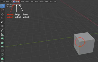
To select vertices in your 3D software, simply click on the one you want. For selecting multiple vertices, hold down the Shift key while clicking on additional vertices. Switching between Vertex Select, Edge Select, and Face Select can be done in the upper-left corner of the interface or by using the 1, 2, and 3 shortcut keys, respectively.
Deletions
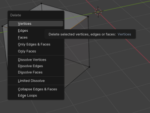
To delete a vertex, edge, or face in your 3D modeling software, select it and then press 'X'. This action will prompt the delete menu to appear, allowing you to choose precisely what you wish to delete.
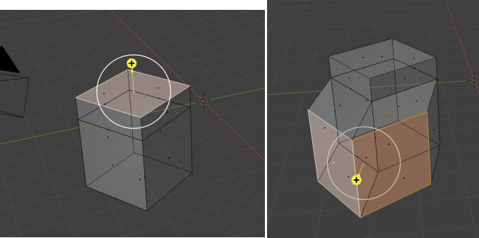
Extrusions
The Extrude Region tool is a fundamental and effective option for editing mesh models. To use it, select the Extrude tool from your toolbar. Then switch to Face Select mode (if not already in it) and click on the face you want to modify. After selecting the face, click and drag the yellow "+" symbol to extrude(bottom left). Additionally, you can utilize the keyboard shortcut 'E' to extrude after selecting the desired face.
We can also extrude an entire region composed of multiple faces(see bottom right). Simply select the faces you want to extrude (hold Shift and click to multi-select) and drag the yellow + symbol.
Sculpting
Sculpting is an ideal technique for creating organic shapes in 3D modeling, utilizing various brushes to push, pull, and deform the object's surface. Be aware that sculpting often generates a mesh with a high number of polygons, especially when adding fine details, which requires a computer with sufficient processing power to handle the intensive workload.
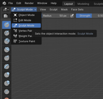
You can enter Sculpt Mode by either clicking on the Sculpting tab at the top of the interface or by selecting it from the Object Mode menu. Once in Sculpt Mode, you'll see that new tools specific to sculpting are now available in the sidebar.
Brush Setting:
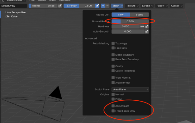
The brush settings in Sculpt Mode can be found on the top or side toolbar, depending on your software layout or version. You can adjust the size of the brush with the "Normal Radius" setting and modify the intensity with the "Hardness" setting. In the top right corner, you have options to toggle symmetry settings across the X, Y, or Z axes, with the default setting typically being symmetrical across the X-axis.
The "Accumulate" and "Front Faces Only" options are useful settings in sculpting. Enabling "Accumulate" allows brush strokes to build up on one another, increasing the effect with each stroke over the same area. Activating "Front Faces Only" restricts the brush's influence to only the vertices visible from the current viewpoint, preventing changes to the mesh's rear side.
Additionally, holding down the Ctrl (or Cmd on Mac) key while using the brush inverts its action. For instance, if the brush is normally adding volume, using Ctrl will switch it to subtract volume, effectively carving into the mesh instead.
Dyntopo:
Dynamic Topology, or Dyntopo, is a feature in Blender that dynamically adjusts the mesh topology as you sculpt. Located in the upper right corner while in Sculpt Mode, turning on Dyntopo allows Blender to automatically create new vertices and faces, giving you the ability to add more detail to your model. This is particularly useful when sculpting intricate details that require a higher resolution mesh.
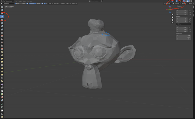
The screenshot above is a modification to the default monkey mesh (Object Mode, Add, Mesh, Monkey) to extrude an abnormal part from the top of the head. It is achieved by using the `Clay Strips` brush with both "Accumulate" and "Dyntopo" enabled. This brush, in combination with these settings, would allow for the addition of volume and complexity to the mesh, resulting in a larger and more detailed head structure.
Subdivision
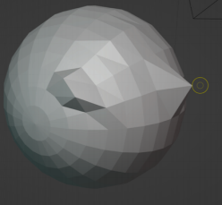
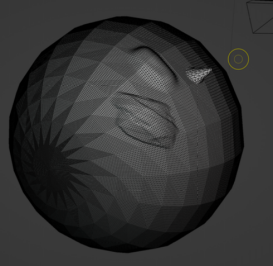
When sculpting on a low-poly model like a sphere with limited stacks and sectors(e.g. the sphere model provided), the effects of the brushes can appear rough, and the manipulation of a single vertex can cause large, spiky deformations due to the lack of sufficient geometry (see screenshot to the right).
To refine the sculpting process, you can subdivide the faces on the sphere to create more geometry. This increases the number of faces, allowing for smoother transitions and finer details as you sculpt. The subdivision process adds vertices, edges, and faces, enhancing the mesh density and providing a better base for sculpting work.
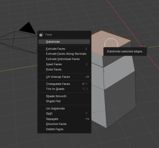
To subdivide any object in Blender, enter Edit Mode and right-click on the object you wish to modify. In the context menu that appears, one of the first options will be "Subdivide". For a sphere, subdividing it 3-4 times is recommended. With each subdivision, you'll notice an increase in the number of triangles covering the surface of the sphere, significantly enhancing its geometry. This process adds more vertices, edges, and faces, providing a smoother and more detailed surface for sculpting and modeling.
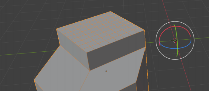
When switching back to Object Mode or Sculpt Mode in Blender after subdividing a mesh, you might observe that the sphere appears to revert to its original, low-poly configuration. This change is simply Blender opting to display the mesh in a more performance-friendly manner, not an actual loss of the subdivisions you applied. The additional faces generated through subdivision remain part of the mesh.
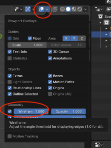
To visually confirm the enhancements and view the detailed structure, including all subdivisions, you can activate the "Wireframe" view option located under "Viewport Overlays". This feature reveals the underlying complexity of the mesh, showcasing the full extent of your modifications (see below).
If you follow operation with the provided sphere, and try to sculpt over the sphere, you should see much more finer brush edits. (See the screenshot below for reference.)
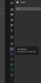
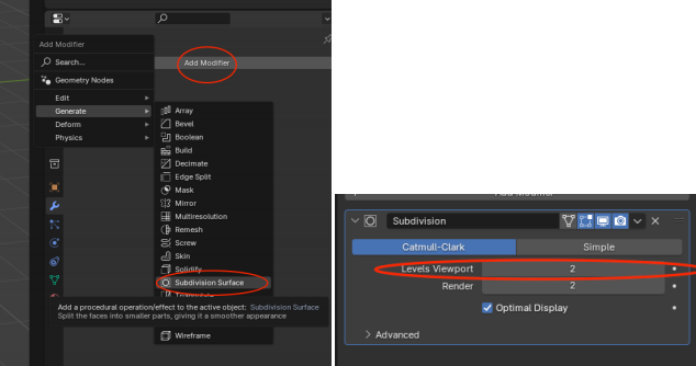
Another method for subdividing your mesh in Blender involves the use of the Modifier panel(see screenshot to the right). In this panel, you can apply a "Subdivision Surface" modifier. This modifier employs an algorithm different from the manual subdivision method discussed earlier. By adjusting the levels of subdivision within the modifier's settings, you can introduce additional subdivisions to the mesh, enhancing its smoothness and detail for more complex sculpting and modeling tasks. This approach allows for non-destructive editing, as it doesn't permanently alter the mesh until applied, offering flexibility in adjusting the mesh's complexity.
Geometry Nodes
Geometry nodes, a relatively new addition to Blender, facilitate procedural modeling through a node-based system, similar to script-based creation. This feature enables the simultaneous addition and alteration of multiple objects, allowing for adjustments in their location, size, and form, as well as the capability to merge them. Given the wide variety of nodes each with unique functions, engaging with tutorials is the most effective strategy for mastering their use.
Click on the ”Geometry Nodes” tab at the top of the Blender window. This tab consists of three windows. The top left panel should show you all the mesh data of your object, starting with the vertex locations. The top right panel is your standard viewport, and the bottom panel is your node graph.
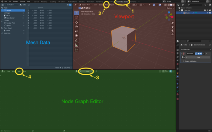
To initiate a new Geometry Node Graph in Blender, press the "+ New" button located in the middle of the node graph panel. This action creates a fresh Geometry Node Graph featuring only an input and output node.
To incorporate additional nodes into your graph, utilize the add button situated in the top left corner of the Node Graph Editor panel. Experimenting with various nodes is encouraged to explore the wide range of possibilities they offer for procedural modeling and manipulation.
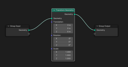
Below is an example of a node, Transform. A node is effectively a function with various kinds of input, and we must have an output at the end. In this case, the input is initial geometry to be transformed an edited, and the output is the new edited geometry that is pushed back into our scene. The numbers in the node itself can either be typed in or generated by another node that’s connected to the blue circles.
How to Submit
As before, you are expected to submit your demo video together with the files and screenshots specified above. In this demo, you will show and also explain how you ran all the steps written above.
Late penalty: 10% for each late day and submission is not allowed after 3 late days.
2024-02-26