CENV3020 GEOTECHNICAL ENGINEERING SEMESTER 1 EXAMINATIONS 2018-19
Hello, dear friend, you can consult us at any time if you have any questions, add WeChat: daixieit
CENV3020W1
SEMESTER 1 EXAMINATIONS 2018- 19
TITLE: GEOTECHNICAL ENGINEERING
Q.1 A new sewage pipe is to be constructed in the base of a trench, cut into an undrained clay soil with side slopes of 45。, as shown in Figure Q1 below.
(i) Define carefully, with the aid of sketches where appropriate, the term “undrained”, as applied to a clay soil. In your answer, explain how the undrained shear strength is related to the specific volume of a clay soil. [6 marks]
(ii) Figure Q1 shows the critical circular arc failure mechanism for the trench. By isolating the sliding soil as a free body, and equating overturning and restoring moments around the centre point, determine the factor of safety on soil strength for the critical mechanism. The geometry of the trench and mechanism, and soil properties, are all given in Figure Q1. Assume that the pipe has not yet been placed in the trench. [8 marks]
(iii) State whether the slope is stable, or unstable, based on the factor of safety that you have calculated. [1 mark]
(iv) A ground investigation at the site identifies a band of soil 0.25 m high and of lower undrained shear strength, running horizontally into the slope from the base of the trench. Explain qualitatively how this would change the calculations that you would need to do to determine the factor of safety for the slope. [4 marks]
[Q1 Total marks = 19]
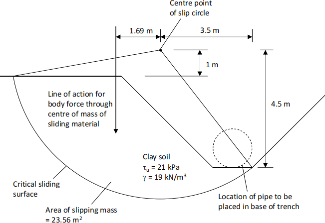
Fig. Q1 Critical failure mechanism for trench in an undrained clay soil
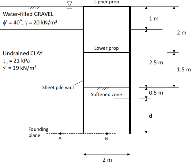
Q.2 Where the sewer pipe runs through the middle of a city, it is to be installed into the base of a trench supported by sheet pile walls, with the walls supported by horizontal steel props, as shown diagrammatically in Figure Q2. The excavation is mainly in clay, except for a shallow depth of saturated gravel close to the ground surface.
(i) An undrained adhesion of 0.5τu is assumed to act at the soil wall interface, meaning that the horizontal total stress in active conditions is given by σh = σv - 2.45τu. Assuming that entirely active conditions form behind the sheet pile wall, show that a flooded tension crack would form to a depth of 4 m below the ground surface. In your calculation, apply a factor of safety of 1.4 to τu. [4 marks]
(ii) Assuming that entirely active conditions form behind the sheet pile wall, and entirely passive in front, calculate the total stress (combined earth and water pressure) distributions that act on the structure.
In your calculation, apply a factor of safety of 1.4 to τu. On the active side, in the gravel soil, assume that the active earth pressure coefficient, Ka, is equal to 0.2218, which is consistent with application of a factor of safety of 1.25 to tanφ’, and δ = φ’ at the soil-wall interface. On the passive side, an undrained adhesion of 0.5τu acts at the soil wall interface so that the horizontal total stress is given by σh = σv + 2.45τu, and assume that softening of the clay takes place at the bottom of the excavation, so that the total horizontal stress at the surface of the excavation is zero, increasing linearly to the full passive resistance at 0.5 m below the base of the excavation. DO NOT apply any additional overdig or surcharges to your calculation. [12 marks]
(iii) Use the earth pressure distribution you determined in part (ii) to calculate the depth of embedment of the walls (defined as ‘d’ in Figure Q2), and the prop load acting in the lower of the two props. As the problem is statically indeterminate, you will need to break the wall into two parts at the level of the lower prop, and analyse each part of the wall separately. [16 marks]
(iv) As the depth of embedment is not very large, there is the possibility for bearing failure around the base of the sheet pile wall. By considering the total vertical stresses acting at the points A and B on the founding plane running through the tip of the wall (all marked in Figure Q2), determine whether the soil below the founding plane is safe in bearing. Apply a factor of safety of 1.4 to τu, and assume that the width of the foundation B is equal to the full width of the excavation (of 2.0 m, as shown in Figure Q2). The equations for bearing capacity are given below. [8 marks]
(v) Suggest three other checks that you might need to carry out to complete the design of the wall. [3 marks]
[Q2 Total marks = 43]
Undrained bearing capacity equations:
(σf - σ0) = (Nc sc dc) τu
Nc = 5.14
sc = 1+ 0.2(B/L)
dc = 1 + 0.23 x V[D/B] up to a maximum of 1.46 (D/B = 4)
B = Width of foundation
D = Depth of foundation
L = Length of foundation
![]()
Fig. Q2 Cross-section through propped sheet pile walls forming excavation for pipe
Q.3 The sewer pipe is to be supported over a ravine by a series of steel ‘A’-frames. The A frames are supported by two square pad foundations, of centres 8 m apart, sitting on alluvial soil at the base of the ravine. The A-frame arrangement is shown in section and plan in Figure Q3.
The combined vertical weight of the A-frame, and the length of pipe and it’s contents supported by each A-frame, is equal to 260 kN. The structure experiences a maximum lateral wind loading that has been simplified to a force of 30kN acting perpendicular to the pipe at point 20 m above ground level, as indicated in Figure Q3.
(i) Calculate the vertical load V, and horizontal load H, acting on the pad footing on the left and right side of the A-frame: (a) when there is no wind force acting, and (b) when the maximum lateral wind force of 30 kN acts. [7 marks]
(ii) Using the equation for the failure envelope for a shallow footing in vertical and horizontal loading given below, determine the maximum vertical load carrying capacity Vmax for each of the two footings, that will allow them to carry the combination of vertical and horizontal loads being applied. In your calculation, apply a factor of safety of 1.25 to tanφ’ . Assume that th = tanδ = tanφ’ . Which is the more critical of the two footings? [8 marks]
(iii) For the more critical footing, use the effective-stress bearing capacity equation given below to determine the width and length of the square footing B required to carry Vmax. Assume that the footings sit on the ground surface (i.e. they are not embedded), and that the water table is as indicated in Figure Q3. In your calculation, apply a factor of safety of 1.25 to tanφ’ . [8 marks]
(iv) Plot onto a graph of H versus V: (a) the factored failure envelope for the most critical footing, and (b) the load path followed by both footings as the lateral wind loading on the structure increases from 0 kN to 30 kN. [8 marks]
(v) If the sewer pipeline was drained for maintenance, the total vertical load of the pipeline and support structure per A-frame would drop from 260 kN to 160 kN. Use your plot in part (iv) above to determine whether the foundations you designed in part (iii) would be satisfactory under the revised loading condition.
If they are not satisfactory, suggest two changes you could make to the foundations and/or A-frame that would ensure they could carry the revised loading condition. [7 marks]
[Q3 Total marks = 38]
Equation for failure envelope for a surface footing in horizontal and vertical loading:
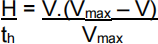
Effective stress bearing capacity equation:

Where:
B = Width of foundation
D = Depth of foundation
L = Length of foundation
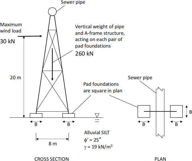
Fig. Q3 Cross-section through A-frame and foundations supporting sewer pipe
2024-01-23