48366 Steel and Timber Design
Hello, dear friend, you can consult us at any time if you have any questions, add WeChat: daixieit
48366 Steel and Timber Design
Design Assignment
Part A: Steel Design
Total Mark: 100 Marks
GENERAL INFORMATION
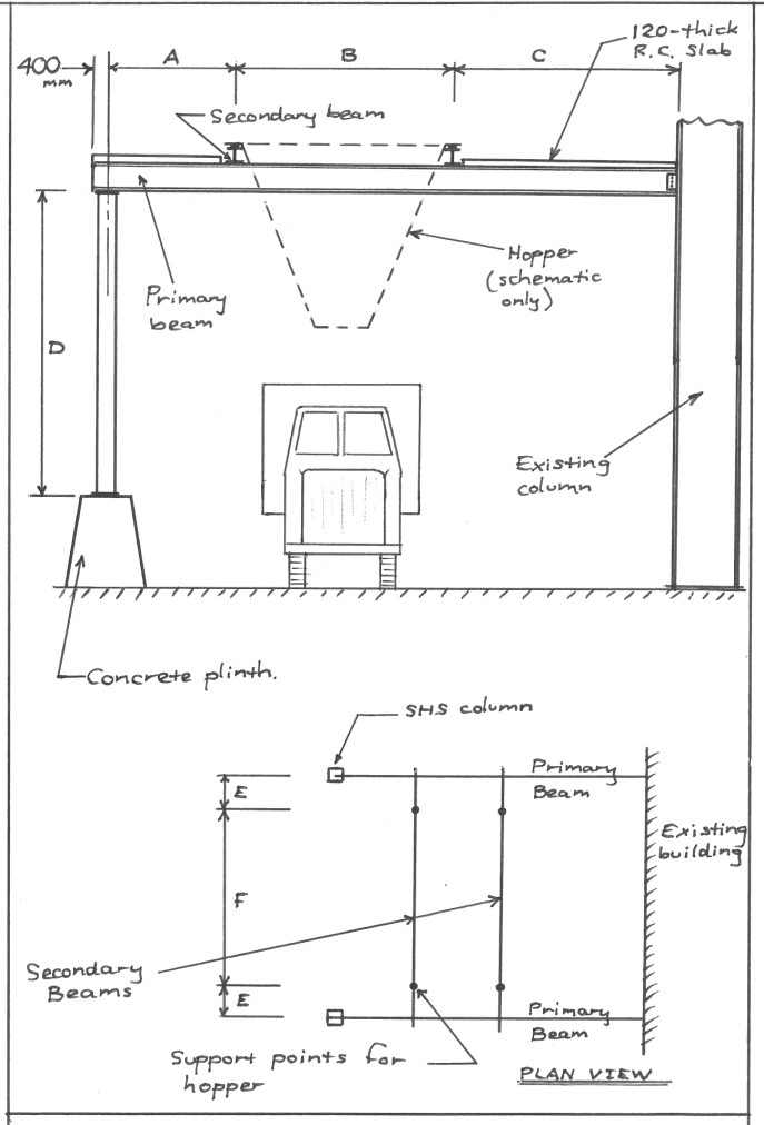
The attached sheet shows preliminary plans for an addition to an existing materials handling facility. A large steel hopper will be suspended from a system of beams which are supported on one side by new steel columns and on the other by existing columns which are part of an existing building.
The hopper hangs from four support points on two secondary beams, which are themselves supported by two primary beams. Trucks drive underneath the hopper for loading.
A tabulation at the end of this document provides data for this exercise.
REQUIREMENTS OF THIS EXERCISE & DESIGN DATA
I. Design of the secondary beams (15 marks)
Determine a suitable size for the secondary beams, using UB or Welded Beam (WB) sections and Grade 300 steel. Note the following:
. Apart from their self weight, each secondary beam carries two concentrated loads from the hopper at a distance of ‘E’ from each end. This load is due to the hopper self weight plus its contents. Data necessary for determination of this loading is provided in the tabulation at the end of this document.
. The secondary beams may be regarded as fully restrained (F) at their ends where they sit on the primary beams. However, since it is conceivable that these beams might buckle simultaneously, with their top flanges moving laterally in the same direction and the hopper moving with them, the load points should not be regarded as restraint points. Hence, these beams each comprise just one segment. In addition, a kl value of 1.4 would be appropriate in this case, in accordance with AS4100 Table 5.6.3(2).
. The web bearing capacity of the secondary beams should be checked at the points where they sit on the primary beams. It may be assumed that the web bearing capacity elsewhere along the secondary beams is satisfactory.
. Since the aesthetics of this support system is not a major issue, deflections are not an important design consideration, but it has been decided that, under maximum loading, beam deflection should not exceed Span length/200.
II. Design of the Primary beams (20 marks)
Determine a suitable size for the primary beams, using UB or WB sections and Grade 300 steel. Note the following:
. A 120mm-thick reinforced concrete slab will be cast on top of the primary beams as depicted. This slab will be ‘locked’ down onto the tops of the beams by the provision of shear connectors which will be welded onto the tops of the beams and cast into the slabs. The shear connectors will restrain any possible lateral buckling of the beam top flange wherever the slabs are located. Allow for a live loading on the slabs of 2 kN/m2. The slabs will be supported by additional steelwork not shown on the diagram and not relevant to this exercise.
. Assume the cross-section of the primary beams at both ends is fully (F) restrained.
. Use the same deflection limitation as specified for the secondary beams, but only the deflection due to the beam self weight and hopper need be considered (i.e. the additional small deflection due to the slab loading maybe neglected).
. The shear capacity of the primary beams should be checked.
. The web bearing capacity of the primary beams should be checked at the points where the secondary beams bear down on them. It maybe assumed that the web bearing capacity elsewhere along the primary beams is satisfactory.
III. Design of the columns (25 marks)
Determine a suitable size for the columns. Note the following:
. The columns maybe designed aspin-ended top and bottom.
. The existing frame is a braced structure.
. This is to be evaluated in accordance with AS4100 Cl. 4.4.2.2. Since the column is being treated as pinned-base, the factor cm will be 0.6 and the effective length factor ke maybe taken as 1.0
IV. Design of the connection at the right-hand end of the primary beams (25 marks)
The connection of the right-hand end of each primary beam to the column of the existing building will utilise a web side plate. For this connection, determine the number and size of bolts required (assume Grade 8.8) and suitable dimensions for the plate. Produce a neat sketch to summarise your design of this connection.
V. Detailing of the connections at the ends of the primary and secondary beams (15 marks)
It has previously been stated that the cross-sections at both ends of the primary and secondary beams should be assumed to be fully (F) restrained. Provide sketches of suitable details which would achieve this (the connection at the right-hand end of the primary beam has already been designed) and briefly explain why this detail achieves a fully restrained (F) cross-section.
DESIGN DATA
|
Material to beheld in hopper |
Raw cane sugar 961 kg/m3 |
|
Volume of hopper (m3) |
56 |
|
Estimated mass of hopper when empty (tonnes) |
5.0
|
|
Dimension ‘A’ |
1.6m |
|
Dimension ‘B’ |
2.8m |
|
Dimension ‘C’ |
3.2m |
|
Dimension ‘D’ |
4.2m |
|
Dimension ‘E’ |
1.0m |
|
Dimension ‘F’ |
5.0m |
ASSESSMENT CRITERIA
The assessment of this exercise will take into consideration:
. Technical correctness;
. Neatness of the presentation and the extent to which diagrams are used to explain the calculations;
. The standard of drawing and amount of information provided on the final diagrams summarising the designs;
. The extent to which cross-referencing is used to clarify where numbers have come from.
2023-10-17