ELEC211 DIGITAL ELECTRONICS AND MICROPROCESSOR SYSTEMS SEMESTER TWO EXAMINATIONS 2018/19
Hello, dear friend, you can consult us at any time if you have any questions, add WeChat: daixieit
ELEC211
SEMESTER TWO EXAMINATIONS 2018/19
DIGITAL ELECTRONICS AND MICROPROCESSOR SYSTEMS
Section A
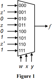
1. a) Find a sum of products expression for the function f given by the circuit in Figure 1 using the 8-to-1 multiplexer. (No simplification required.)
b) Design a circuit for the following expressions using a BCD to decimal decoder and two OR gates. You need to first decide the least and most significant bits of input (indicate these on your diagram.)
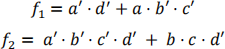
c) Decompose the following function into 4 functions for e’d’, e’d, ed’ and ed.

d) An ASM chart for a finite state machine is shown in Figure 2. Construct a state transition table using the one hot state representation. (The code for each state is shown on the top right of the state box.)
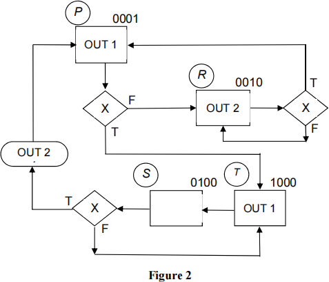
e) For the ASM chart shown in Figure 2, design simplified Boolean equations for the outputs and next state logic, assuming D-type flip flops are used. A circuit diagram is not required.
Total 25
2 a) Use the Quine-McCluskey method to minimise the following Boolean expression:

Where m represents the minterms for which f must be true and the terms following d are “don’t care”. The least significant bit is e. Your solution should include:
i) The detailed procedure to determine the Prime Implicants.
ii) The Prime Implicant chart used for the potential elimination of some of the Prime Implicants.
iii) A list of the essential Prime Implicants and the final Boolean minimum sum of products expression.
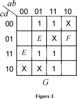
b) Find the minimum sum of products expression for the function G given by the following Karnaugh map (Figure 3) with map entered variables E and F.
Total 25
Section B
3. a) Explain the following address modes: immediate addressing, register addressing and indirect addressing.
b) Assume that the following registers initially hold the values given:
r3: 0x0310F027
r4: 0xE3D62F27
r5: 0x3B51048D
r6: 0xA0913C29
r7: 0x9A404A07
Find the values held in registers r1, r2, r3 and r4 after the following ARM Cortex M0 instructions are executed?
i) SUBS r1, r6, r7
ii) ORRS r2, r6, r5
iii) ADDS r3, r3, r5
iv) REV r4, r6
c) Find the 32 bit two's complement format for the decimal numbers –12510 and –1,251,251,25110. (Note that 0x4A949433 is the hexadecimal equivalent of +1,251,251,25110.)
d) Find the IEEE 754 floating point format (single precision) for the decimal numbers, –125.510 and +12.310.
e) Find the decimal number that is equivalent to 0xC2200000 in the IEEE754 floating point format.
Total 25
4. a) The ARM Cortex M0 microprocessor has four flags, namely N (negative), Z (zero), C (carry) and V (overflow).
Explain what each of these flags would indicate if it was set.
b) What is the state of the flags after the execution of the instruction: ADDS r2, r5, #0x001F4000 ; add 2,048,000 to r5, put sum in r4
i) when the value held by r5 is 0x00E0B000
ii) when the value held by r5 is 0x800F4000
iii) when the value held by r5 is 0xFFE0C000
c) The carry flag can be used in two different ways; explain both uses of the carry flag.
d) Demonstrate how the carry flag can be used to add two positive integers if the integers are greater than 4.3x10⁹ e.g. 6x10¹⁰ + 6x10¹¹ (0x0000000D F8475800 + 0x0000008B B2C97000)
Total 25
2023-08-24