MMAN2300 T2 2023 Engineering Mechanics 2
Hello, dear friend, you can consult us at any time if you have any questions, add WeChat: daixieit
Engineering Mechanics 2
MMAN2300 T2 2023
Coriolis Laboratory Assignment
Assignment Due: 5 PM (Sydney time) Friday, 14 July 2023
Purpose: The purpose of this lab activity is to help you have a good understanding of the Coriolis concept and demonstrate your understanding by completing the tasks and your individual report.
Skills: The purpose of this lab exercise is to help you practice the following skills that are important in achieving the learning outcomes of the course. In this exercise you will:
· Apply the knowledge learned on the topic of acceleration analysis of rigid bodies to complete the required tasks
· Compose a clear and concise report/assignment using the provided template
Knowledge: This lab exercise will also help you become familiar with the following important knowledge in the course.
· Planar motion of rigid bodies, in particular, Coriolis component
· Analysis of the motion using a fixed and/or rotating reference frame
General instructions
Use this template to complete the Coriolis Lab Assignment, which has three parts. Part 1 of the assignment can be completed by handwriting or typing. Part 2 and Part 3 MUST be completed by typing, unless otherwise specified. Any handwritten text in Part 2 and Part 3 will not be marked. All parts must be completed to achieve full mark. Use the space provided in the boxes of this document to report your answers.
It is recommended to use 11-point Times New Roman font.
You must use your zID to run the simulation.
Situation description
You work for a consulting firm that provides solutions to machinery problems. A client has requested for your assistance to solve some issues with a mechanism of their machine. The following is the email you have received from the client.
Email from client
Hi,
As mentioned on the phone earlier, we need your assistance in troubleshooting a mechanism of our machine. I have included some information regarding the mechanism and its issues in this email. The following is a diagram of the mechanism.
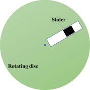
A slider is constrained to move radially along the groove while the disc rotates about its own centre of mass (fixed). This mechanism is however faulty and requires maintenance before it can operate properly. The problems are:
1) The speed indicator of the rotating disc is not accurate and requires calibration.
2) The speed of the slider relative to the groove is unknown.
3) Due to problem (2), it is difficult to estimate the exact time to stop the mechanism before the slider reaches the end of the groove (and collides with the wall of the groove).
To help with the investigation of the problems, we have mounted sophisticated motion sensors on the slider. The motion sensors are capable of measuring (i) the position of the slider with respect to (w.r.t.) the centre of the disc, (ii) the absolute velocity of the slider, and (iii) the absolute acceleration of the slider.
Note that the slider can be treated as a particle and the measured distance from the centre of the disc to the end of the groove is 900 mm. We have also mounted two cameras – Camera 1 on the stationary fixed support and Camera 2 on the rotating disc (i.e., rotating with the disc), as we thought some video recordings from the two cameras might be of interest for your analysis. Finally, I have attached a form below and we would appreciate it if you can report the results of your analysis and your suggestions using the form.
Look forward to hearing from you!
Regards,
Client
Part 1. Velocity and acceleration analysis
|
Part 1 Ref. Report a screenshot of the ‘photo’ you have obtained from the program, showing the given instant of motion and the parameters provided. Note that this step is just for reference and no mark is awarded. |
|
Part 1A. Based on the position and motion of the mechanism at the particular instant shown in Part 1 Ref, find: (i) the angular velocity (magnitude and direction) of the rotating disc (note that the angular velocity provided by the speed indicator in Part 1 Ref is inaccurate and you are required to find its accurate value using the data obtained from the motion sensors), (ii) the velocity (magnitude and direction) of the slider relative to the rotating disc, (iii) the Coriolis acceleration (magnitude and direction), (iv) the angular acceleration (magnitude and direction) of the rotating disc, and (v) the acceleration (magnitude and direction) of the slider relative to the rotating disc. For (iv) and (v), note that the angular velocity of the disc and the velocity of the slider relative to the disc are not constant in Part 1. |
|
|
Final answer for (i): |
Final answer for (ii): |
|
Final answer for (iii): |
Final answer for (iv): |
|
Final answer for (v): |
|
|
Part 1B. Compare your result in Part 1A(i) and the value from the speed indicator of the rotating disc (from ‘photo’) by calculating the percentage error between the angular speed obtained from Part 1A(i) and the one from the speed indicator. |
|
Final answer for percentage error: |
|
Part 1C. Based on the results calculated from previous parts, determine (i) When the mechanism should be stopped before the slider collides at the end of the groove, i.e., how long it takes for the slider to reach (right before touching) the end of the groove from the instant of motion shown in the ‘photo’? The slider can be treated as a particle by neglecting the dimensions of the slider. (ii) The angular displacement of the rotating disc just when the slider reaches the end of the groove. Assume that the magnitude of the disc’s angular acceleration and the magnitude of the slider’s acceleration relative to the disc obtained in Part 1A are constant. |
|
|
Final answer for (i):
|
Final answer for (ii): |
Part 2: Investigation of Coriolis effect (with zero angular acceleration of the disc and zero acceleration of the slider relative to the disc)
Study the ‘short videos’ using the program (a) under different combinations of operating conditions by changing the angular velocity (magnitude and direction) of the rotating disc and/or the velocity of the slider relative to the disc, and (b) from different reference frames, that is, a fixed frame to ground and a rotating frame fixed to the disc.
|
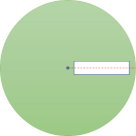
Figure 2A. The initial position of the disc for the activities in Part 2A
Part 2A. Draw qualitatively the trajectory of the slider when it moves from the initial position (given in the program*) to the position where the slider reaches the other end of the groove, for the two cases requested, viewed from Camera 1 (fixed to ground). Note that the initial position of the disc is shown in Figure 2A, where the groove is horizontal rightward. Also, briefly justify the reasons for the trajectories you draw. (*Once you run the program, click the third button ‘What do I need to predict?’ to obtain further information regarding the two cases.) |
|
|
Case 1 Write the conditions of your case here |
Case 2 Write the conditions of your case here |
|
Place your drawing for Case 1 here (hand-drawing is allowed as long as it’s legible) |
Place your drawing for Case 2 here (hand-drawing is allowed as long as it’s legible) |
|
Briefly justify your drawing for Case 1 here |
Briefly justify your drawing for Case 2 here |
|
Part 2B. Based on your observations in Part 2A and your understanding of Coriolis effect, briefly discuss:
(i) the effect of the magnitude of the disc’s angular velocity on Coriolis acceleration, and draw a graph* that shows the trend of (ii) the effect of the direction of the disc’s angular velocity on Coriolis acceleration.
(iii) the effect of the magnitude of the slider’s velocity relative to the disc on Coriolis acceleration, and draw a graph* that shows the trend of (iv) the effect of the direction of the slider’s velocity relative to the disc on Coriolis acceleration. (v) the difference between trajectories of the slider viewed from the fixed and rotating reference frames. *Note: the requested graphs are just qualitative sketches of trends. |
|
Part 3: A conceptual problem
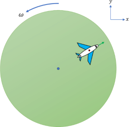
The slider is replaced with an airplane and the groove no longer exists. In the diagram shown, the airplane is about to take off from the rotating platform. Before taking off, it has a constant velocity relative to the rotating platform. Considering only motion in the x-y plane and given that the magnitude of |
2023-07-12