ELEC0010 Examples of SystemVerilog modules describing digital building blocks
Hello, dear friend, you can consult us at any time if you have any questions, add WeChat: daixieit
ELEC0010 Examples of SystemVerilog modules describing digital building blocks
Contents
1. D-flip flops
2. Register
3. Register file
4. Read only memory (ROM)
5. Arithmetic logic unit
6. Counter
7. Testbench to test register module
1. D-flip flops
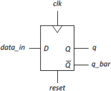
The example code below implements a D-flip flop with active positive clock edge and active- high synchronous reset (the flip flop resets only when a positive clock edge is applied).
module dff (input logic data_in, reset, clk,
output logic q, q_bar);
assign q_bar = ~q;
always_ff @ (posedge clk)
begin
if (reset) q <= 0;
else q <= data_in;
end
endmodule
The example code below implements a D-flip flop with active positive clock edge and active- high asynchronous reset (the flip flop resets whenever the reset input is asserted).
module dff (input logic data_in, reset, clk,
output logic q, q_bar);
assign q_bar = ~q;
always_ff @ (posedge clk or posedge reset)
begin
if (reset) q <= 0;
else q <= data_in;
end
endmodule
2. Register
The following code describes an 8-bit register:
module regist (input logic [7:0] data_in,
input logic clk,
output logic [7:0] data_out);
always_ff @ (posedge clk)
data_out <= data_in;
endmodule
3. Register file
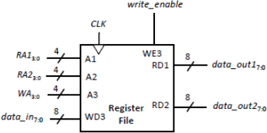
This register file has sixteen 8-bit registers. The contents of any two of the registers (with addresses specified by the 4-bit inputs RA1 and RA2) are continuously output as data_out1 and data_out2. On the positive edge of the clock , if write_enable is asserted, the input data_in is written into the register at address WA.
module reg_file(input logic [3:0] RA1, RA2, WA,
input logic [7:0] data_in,
input logic clk, reset, write_enable,
output logic [7:0] data_out1, data_out2);
logic [7:0] rf [0:15];
assign data_out1 = rf[RA1];
assign data_out2 = rf[RA2];
always_ff @ (posedge clk)
if (write_enable)
rf[WA] <= data_in;
endmodule
4. Arithmetic logic unit (ALU)
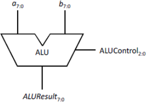
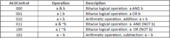
This example of an ALU carries out bitwise logical operations, addition and subtraction operations, according to the table below.
module alu(input logic [7:0] a,
input logic [7:0] b,
output logic [7:0] ALUResult,
input logic [2:0] ALUControl);
always_comb
case(ALUControl)
3'b000 : ALUResult = a & b; // bitwise a AND b
3'b001 : ALUResult = a | b; // bitwise a OR b
3'b010 : ALUResult = a + b; // addition a + b
3'b100 : ALUResult = a & ~b; // bitwise a AND (NOT b)
3'b101 : ALUResult = a | ~b; // bitwise a OR (NOT b)
3'b110 : ALUResult = a - b; // subtraction a - b
default : ALUResult = 8'bx;
endcase
endmodule
The arithmetic operations assume negative values are represented in two’s complement. The most significant bit indicates the sign of the number (0 for positive numbers, 1 for negative numbers). Conversion between positive and negative values is carried out by inverting the bits, and adding one.
Example - represent -4510 in 8-bit two’s complement form:
• Start with the representation of +4510 : 00101101.
• Invert the bits and add 1: -4510 = 11010011
5. Read-Only Memory (ROM) array
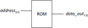
The synthesisable code example below implements a ROM array, storing 16 words of data, with each word being 8 bits wide. The data to be stored is read in from a text file, in a single pass behaviour (keyword initial), using the $readmemh system task. In the example below, the text file name ‘rom.txt’ has been chosen; any file name ‘*.txt’, without spaces, can be used. The text file should be stored in the same folder as the SystemVerilog modules.
module rom(input logic [3:0] address,
output logic [7:0] data_out);
logic [7:0] data_ROM [0:15];
initial
$readmemh(“rom.txt”, data_rom);
assign data_out = data_ROM[address];
endmodule
Shown below is an example of the text file ‘rom.txt’ containing the 16 words of data (each word is 8-bits wide) to be stored in the ROM. The data is written in hexadecimal form:
02
E4
75
2A
CE
35
D1
97
56
F2
A4
B0
01
89
F5
A7
Note: The values in the text file could alternatively be written in binary rather than hexadecimal; in this case, the system task $readmemb should then be used in the ROM module.
6. Counter
The following describes an 8-bit counter with active-high reset. The value of count increments on each rising edge of the clock.
module counter(input logic clk, reset,
output logic [7:0] count);
always_ff @ (posedge clk) begin
if (reset) count <= 8'b0;
else count <= count + 1;
end
endmodule
7. Testbench
The following is an example of a testbench to the test the register file module in section 3:
`timescale 1ps/1ps
`include "reg_file.sv"
module reg_file_tb;
logic [3:0] RA1, RA2, WA;
logic clk, reset, write_enable;
logic [7:0] data_in, data_out1, data_out2;
reg_file dut (RA1, RA2, WA, data_in, clk, reset, write_enable, data_out1, data_out2);
initial begin // Generate clock signal with 20 ns period
clk = 0;
forever #10 clk = ~clk;
end
initial begin // Apply stimulus
$dumpfile("reg_file_tb.vcd");
$dumpvars(0, reg_file_tb);
RA1 = 1; RA2 = 2; WA = 0; data_in = 5; write_enable = 0;
reset = 1;
#10 reset = 0;
#15 write_enable = 1;
#20 WA = 1; data_in = 7;
#20 WA = 5; data_in = 13;
#20 write_enable = 0;
#20 RA2 = 5;
#30;
$finish; // This system tasks ends the simulation
end
initial begin // Response monitor
$monitor ("t = %3d, clk = %b, reset = %b, RA1 = %b RA2 = %b, \
WA = %b, write_enable = %b, data_in = %b, data_out1 = %b, \
data_out2 = %b", $time, clk, reset, RA1, RA2, WA, write_enable, data_in, data_out1, data_out2);
end
endmodule
Note that a string literal can be extended onto the next line, provided the new line is immediately preceded by a \ (backslash). This is used in the response monitor block in the above example, to make the code more readable in the source code editor.
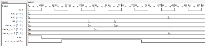
The resulting simulation waveforms from the reg_file_tb testbench are shown below.
2023-05-28