ECE391: Computer Systems Engineering Spring 2023 Machine Problem 2
Hello, dear friend, you can consult us at any time if you have any questions, add WeChat: daixieit
ECE391: Computer Systems Engineering
Spring 2023
Machine Problem 2
CP1 due in Gitlab repo by 5:59 PM CST on Monday 27 February
CP2 due in Gitlab repo by 5:59 PM CST on Monday 6 March
Device, Data, and Timing Abstractions
Read the whole document before you begin, or you may miss points on some requirements.
In this machine problem, you will extend a video game consisting of about 4,000 lines of code with additional graphical features and a serial port device. The code for the game is reasonably well-documented, and you will need to read and understand the code in order to succeed, thus building your ability to explore and comprehend existing software systems. Most code that you will encounter is neither as small nor as well documented—take a look at some of the Linux sources for comparison—but this assignment should help you start to build the skills necessary to extend more realistic systems. As your effort must span the kernel/user boundary, this assignment will also expose you to some of the mechanisms used to manage these interactions, many of which we will study in more detail later in the course. Before discussing the tasks for the assignment, let’s discuss the skills and knowledge that we want you to gain:
• Learn to write code that interacts directly with devices.
• Learn to abstract devices with system software.
• Learn to manipulate bits and to transform data from one format into another.
• Learn the basic structure of an event loop.
• Learn how to use the pthread API.
Device Protocols: We want you to have some experience writing software that interacts directly with devices and must adhere to the protocols specified by those devices. Similar problems arise when one must meet software interface specifications, but you need experience with both in order to recognize the similarities and differences. Unfortunately, most of the devices accessible from within QEMU have fully developed drivers within Linux. The video card, however, is usually managed directly from user-level so as to improve performance, thus most of the code is in other software packages (e.g., XFree86).
We are fortunate to have a second device designed by Kevin Bassett and Mark Murphy, two previous staff members. The Tux Controller is that funny little game controller attached to each of the machines in the lab.
The Tux Controller connects to the USB port of the lab machine. An FTDI“Virtual Com Port”(VCP) driver makes the USB port appear to software as a standard (old fashioned) RS232 serial port. We can then set up QEMU so that one of the emulated serial ports on the virtual machine maps to the emulated serial port connected to the Tux Controller. In this assignment, you will write code that interacts directly with both the (emulated) video card and the game controller board.
Device Abstraction: Most devices implement only part of the functionality that a typical user might associate with them. For example, disk drives provide only a simple interface through which bits can be stored and retrieved in fixed-size blocks of several kB. All other functionality, including everything from logical partitions and directories to variable-length files and file-sharing semantics, is supported by software, most of which resides in the operating system. In this machine problem, you will abstract some of the functionality provided by the Tux controller board.
Format Interchange: This machine problem gives you several opportunities for working with data layout in memory and for transforming data from one form to another. Most of these tasks relate to graphics, and involve taking bit vectors or pixel data laid out in a form convenient to C programmers and changing it into a form easily used by the Video Graphics Array (VGA) operating in mode X. Although the details of the VGA mode X layout are not particularly relevant today, they do represent the end product of good engineers working to push the limits on video technology. If you work with cutting-edge systems, you are likely to encounter situations in which data formats have been contorted for performance or to meet standards, and you are likely to have to develop systems to transform from one format to another.
Event Loops: The idea of an event loop is central to a wide range of software systems, ranging from video games and discrete event simulators to graphical user interfaces and web servers. An event loop is not much different than a state machine implemented in software, and structuring a software system around an event loop can help you to structure your thoughts and the design of the system.
Threading: Since the advent of faster processors, it became possible to exploit code parallelism by creating multiple threads. Multiple threads of execution also allow logical separate tasks to be executed using synchronous operations. If one thread blocks waiting for an operation to complete, other threads are still free to work. Note that threads are different from processes. A thread is the smallest unit of processing that can be scheduled by an operating system. Multiple threads can exist within the same process and share resources such as memory. Different processes cannot share these resources. On a single processor, multithreading generally occurs by having the processor switch between different threads, which is known as context switching. Since context switching happens frequently, the user perceives the threads as running concurrently.
In this machine problem, we illustrate the basic concepts by using a separate thread to get updates from the keyboard. You will need to synchronize your code in the main thread with this helper thread using a Posix mutex. You will also need to add a new thread to take input from the tux controller. This thread may also need synchronization to guarantee correctness.
You may want to read the class notes on Posix threads to help you understand these interactions. Later classes will assume knowledge of this material.
Software examples and test strategies: In addition to these five learning objectives for the assignment, this machine problem provides you with examples of software structure as well as testing strategies for software components.
Two of the files include main functions that are only included when a defined value is changed at the top of the file. By setting this value to one and compiling the file by itself, you create an executable that tests the functionality provided by the file in the absence of other code. When you design software interfaces, you should do so in a way that allows you to test components separately in this manner and thus to deal with bugs as soon as possible and in as small a body of code as possible. Individual function tests and walking through each function in a debugger are also worthwhile, but hard to justify in an academic setting. The input control file allows you to develop and test your Tux controller code without using the game interface. Since the game changes the display to mode X, testing without the hassle of changing back to text mode can be quite helpful.
The modex .c file is compiled by the Makefile to create a separate executable that returns your system to text mode. We also made use of a technique known as a memory fence to check some of the more error-prone activities in the file; read the code to understand what a memory fence is and what it does for you.
The Pieces Provided
You are given a working but not fully-functional copy of the source tree for a maze game along with a skeletal kernel
module for the Tux controller. The Tux controller boards are attached to each machine in the lab. The table below explains the contents of the source files.
|
assert .c |
Support for assertions and cleanups as design and debugging aids. |
|
blocks .s |
Graphic block images of the maze, the player, fruits, etc. |
|
input .c |
Input control. Provides for initialization and shutdown of the input controller. The version provided to you supports keyboard control. You must write the support for the Tux controller. This file is not compiled with the rest of the game and should be used only to test your inputs separately from the game. Can be compiled stand-alone to test the input device. |
|
maze .c |
Maze generation and logic. Creates the maze; creates, checks for, and consumes fruit; checks for win conditions. Transforms the block image data in blocks .s into pixelized graphic images of maze lines and columns for use by modex .c in drawing parts of the logical view. Can be compiled stand-alone to test maze generation. |
|
mazegame .c |
Multithreaded main process of the mazegame. There is a thread that controls the game logic, includ- ing the main event loop, level set up, all timing logic, display control logic (motion and scrolling). Includes a computer-controlled player as well as one using the regular input control. Another thread is created to handle keyboard control. You will eventually need to add another thread for the Tux Controller control. |
|
modex .c |
Functions to support use of VGA mode X. Includes things like switching from text mode to mode X and back, and clearing the screens. Provides a logical view window abstraction that is drawn in normal memory and copied into video memory using a double-buffering strategy. When the logical view is shifted, data still on the screen are retained, thus only those portions of the logical view that were not previously visible must be drawn. Finally, supports mapping from pixelized graphics in formats convenient to C into drawing a screen at a certain logical position. Relies on maze .c to provide vertical and horizontal lines from the maze. Is also compiled stand-alone to create the tr text mode restoration program. |
|
text .c |
Text font data and conversion from ASCII strings to pixelized graphic images of text (you must write the latter). |
We have also included two stripped binaries to illustrate your end goal. The mazegame-demo program is a fully working version of the game that allows both keyboard and Tux controller input. The input-demo program is a stand-alone compilation of input .c, again allowing both forms of input.
The tr Program
The make file provided to you builds both the game and a text-mode-restoration program called tr. The latter program is provided to help you with debugging. One difficulty involved with debugging code that makes use of the video hardware is that the display may be left in an unusable (i.e., non-text-mode) state when the program crashes, hangs, or hits a breakpoint. In order to force the display back into text mode for debugging purposes (or, if you are not running the program in a debugger, to regain control of your shell), you can run the tr program. Unless you are fairly confident in your ability to type without visual feedback, we recommend that you keep a second virtual console (CTRL-ALT-F1 through F6) logged in with the command to execute the text restoration program pre-typed, allowing you to simply switch into that console and press Enter. Using this program is substantially easier than rebooting your machine to put it back into text mode.
You should also look at the cleanup handlers provided by the assert module (assert .h and assert .c). These cleanup handlers provide support for fatal exceptions, putting the machine back into a usable state when your program crashes. However, there may be instances and problems not covered by the handlers, and GDB can stop the program before the handlers are invoked, leaving the machine in an unusable state until you restore text mode with tr.
Mode X and Graphic Images
Mode X is a 256-color graphics mode with 320x200 resolution. It was not supported by the standard graphics routines that came with the original VGAs, but was supported by the VGA hardware itself, and was quickly adopted as the stan- dard for video games at the time because of certain technical advantages over the documented 256-color mode (mode 13h, where the‘h’stands for hexadecimal). In particular, mode X supports multiple video pages, allowing a program to switch the display between two screens, drawing only to the screen not currently displayed, and thereby avoiding the annoying flicker effects associated with showing a partially-drawn image. This technique is called double-buffering.
Each pixel in mode X is represented by a one-byte color value. Although only 256 colors are available in mode X, the actual color space is 18-bit, with 6-bit depth for red, green, and blue saturation. A level of indirection is used to map one-byte pixel color values into this space. The table used in this mapping is called a palette, as it is analogous to a painter’s palette, which in theory holds an infinite range of colors, but can only hold a few at any one time. Palettes are often used to reduce the amount of memory necessary to describe an image, and are thus useful on embedded devices even today. For your final projects, some of you may want to play with graphic techniques such as palette color selection to best represent a more detailed image and dithering to map a more detailed image into a given palette.
The mapping between screen pixels and video memory in mode X is a little contorted, but is not as bad as some of the older modes. The screen is first separated into blocks four pixels wide and one pixel high. Each block corresponds to a single memory address from the processor’s point of view. You may at this point wonder how four bytes of data get crammed into a single memory address (one byte in a byte-addressable memory). The answer, of course, is that they don’t. For performance reasons, the VGA memory was 32-bit, and the interface between the processor and the VGA is used to determine how the processor’s 8-bit reads and writes are mapped into the VGA’s 32-bit words. For example, when the processor writes to a memory address, four bits of a specific VGA register are used to enable (1 bits) or disable (0 bits) writes to 8-bit groups of the corresponding word in VGA memory. When drawing rectangles of one color, this mask reduces the work for the processor by a factor of four. When drawing images, however, it poses a problem in that adjacent pixels must be written using different mask register settings. As changing a VGA register value is relatively slow, the right way to use mode X is to split the image data into four groups of interleaved pixels, set the mask for each group, and write each group as a whole using the x86 string instructions (you won’t need to write any of these, although you may want to look at how it is done in the existing code or in the x86 manual).
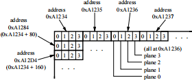
Mode X video memory is memory-mapped and runs from (physical) memory address 0xA0000 to 0xAFFFF, for a total of 216 addresses and 256 kB of addressable memory (counting all four planes). The addresses used in your program are virtual rather than physical addresses, a concept to be discussed later in the course; don’t be surprised if they are not the same as the physical addresses, though. A full screen occupies 320 × 200/4 = 16, 000 addresses, so four fit into the full memory, with a little extra room. The VGA can be directed to start the display from any address in its memory; addresses wrap around if necessary. In the figure shown above, for example, the screen starts at address
0xA1234.
Due to the timing behavior of emulated interactions with video memory, the code provided to you does not use a traditional double-buffering model in which the off-screen image is drawn directly within video memory. As with double-buffering, we do maintain two regions within the video memory for screen images. However, we use regular memory to maintain an image of the screen and to update that image in place. When a new image is ready for display, we copy it into one of two regions of the video memory (the one not being displayed) and then change the VGA registers to display the new image. Copying an entire screen into video memory using one x86 string instruction seems to take about as long as writing a small number of bytes to video memory under QEMU, thus our image display is actually faster than trying to draw a vertical line in video memory, which requires one MOV instruction per vertical pixel.
Only the modex .c file relies on mode X. The rest of the code should use a graphics format more convenient to C. In particular, an image that is X pixels wide and Y pixels high should be placed in an array of dimensions [Y][X]. The type of the array depends on the color depth of the image, and in our case is an unsigned char to store the 8-bit color index for a pixel. The block images in blocks .s already use this format, as do the line generation routines in maze .c. When you write code to generate graphic images from text, as described in a later section, you should use the same format.
Graphical Mapping in the Game
The game defines a two-dimensional world of pixels, and the screen at any time shows a region of that world. The maze world is never fully constructed in memory; rather, it is constructed dynamically as necessary to fill the screen.
This facet is useful for games in which drawing the entire virtual world at once requires too much memory. build buffer
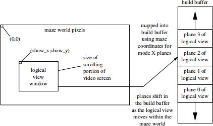
We use a build buffer to keep the pixel data relevant to the screen organized in a form convenient for moving into video memory in mode X. However, in order to avoid having to move the data around a lot in the build buffer (or redraw the whole screen each time we move the logical view window by one pixel), we break the maze world into 4x1 pixel chunks using the mode X mapping illustrated in the previous section. The address of the logical view window in the maze world is used to decide where to place the image planes within the build buffer, and moves around within the build buffer as the logical window moves in the maze world, as shown in the figure below.
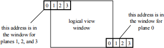
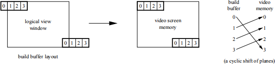
The next problem is mapping the build buffer into the video memory. We use two buffers in video memory and map into the non-displayed buffer, then change the VGA register to show the new screen. You can read about this double- buffering technique in the code and see how it works. The complexity with regard to the plane mapping is that we must map the build buffer planes, which are defined in terms of the maze world coordinates, into the video planes, which are defined in terms of the screen coordinates. The picture below illustrates this problem. In general, a cyclic shift of the planes suffices for the mapping.
The next question is the size of the build buffer. If we can limit the size of the maze world, we can allocate a build buffer large enough to hold any logical view window. If the window starts at pixel (0,0) in the maze world, plane 3 is placed at the beginning of the build buffer. If the window occupies the lower right corner of the maze world, plane 0 is placed at the end of the build buffer. Such calculations are not particularly hard.
However, we do not want to restrict the size of the maze world, so we add a level of indirection and move the relative offset of the logical view window within the build buffer as the logical view shifts within the maze world. The maze world can thus be of almost arbitrary size, and is limited only by the size of the coordinate types (32-bit indices).
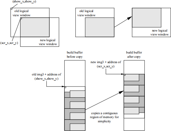
The img3 and img3 off variables provide the additional level of indirection. At any point in time, adding the address calculated from the logical view window coordinates (show x,show y) to the img3 pointer produces a pointer to the start of plane 3 in the build buffer. However, the actual position of that plane in the build buffer may change over time. Whenever a new logical view window setting is requested, the code checks whether all four planes of the new window fall within the build buffer boundaries. If they do not, the window is repositioned within the build buffer in order to make it fit. To minimize copying, the planes of the new window are centered within the build buffer. The figure at the bottom of the previous page illustrates the process.
Finally, we add a memory fence to the build buffer to ensure that we didn’t screw up the copying calculations. Read about it in the code.
A Few Preliminaries
Obtain a copy of the MP2 starting code. As with MP1, you will be given access to your Git repository shortly after the MP is released. Watch your @illinois.edu email for an invitation from Gitlab. Refer to MP1 documents for the proper git commands. We suggest that you check out the files in the work directory (Z drive or /workdir): when working with the Tux controller code, both of your virtual machines will need access to the files, and keeping them on the work directory server means that you don’t have to copy them around as often.
Read the code and understand it. We will ask you questions about the code as part of the demo, and will also test your conceptual understanding of the techniques used in the code during examinations. Don’t be shy about asking questions on Piazza, but do be careful so as not to give away MP answers. For example, it’s ok to ask and answer questions about memory fences or other code given to you, but it’s not ok to give code or pseudo-code for writing a vertical line to the mode X build buffer (one of the tasks below).
We expect you to follow good software engineering practices in your code. Variables should almost never be global. On the other hand, don’t go parameter-happy: file scope variables are fine. The code given to you has one global variable, which contains the font data for restoring text mode and for drawing text as graphic images while in graphics mode. Buffers passed to functions should either be fixed-size, or the available space should be passed and checked. Everything should be clearly thought out and well-commented. Functions should have function headers. Prototypes and variables should be organized, not scattered about the files. Indentation must be done correctly.
The Checkpoint
The order presented here is only a suggestion, but we do strongly recommend that you read the code first, that you tackle the parts one at a time rather than working on them all at once, that you commit working versions to your repository as you get each part working, and that you start with the easier parts. You must do all of these things for the first checkpoint. Other parts of the final MP are optional at the first checkpoint, and will not serve to make up points for missing required functionality.
Write the vertical line drawing routine in modex .c. Everything but the function body is already in place for you (even the function header!), and you can look at the horizontal line drawing routine right next to it, so this part should be an easy place to start. The main difficulty is for you to understand both how mode X maps pixels and how the abstractions in modex .c work, so try to read the code and documentation to the point that you feel you understand these things, then try to write the function with the help of the examples.
Find the VGA documentation for the status bar. Doing so was part of PS2, and you can work together and discuss how it should be done, but not trade code to do it.
Add the status bar to the game. It should be big enough to allow you to write a line of text with an extra pixel above and below. How big is that? Read the code. Defined constants have been cleverly included to reduce the amount of work for you (see IMAGE versus SCROLL dimensions in the code), but you will have to shift a couple of bits of the existing code around here and there because of VGA constraints.
Write a text to graphics image generation routine in text .c. Given a string, it should produce a buffer that holds a graphical image of the ASCII characters in the string. The height of the buffer is fixed. You may either (a) figure out how much text fits on the status bar and produce a buffer of fixed-size, or (b) return the resulting image width. In either case, the text must be centered on the bar, in case (a) by this routine, and in case (b) by the next routine. Don’t forget to put a prototype and explanation into text .h.
Write a routine to put a graphic image, and in particular, the output of routine described in the previous paragraph, on to the status bar.
Put the level number, number of fruits, and clock (using minutes and seconds since the level was started, as shown in the demonstration version) on the status bar.
You will notice that the player is surrounded by black pixels and leaves a trail in the code provided to you, whereas the player is drawn on top of the normal maze floor and does not leave a trail in the demo version of the game. This effect is accomplished by a technique known as masking, in which a separate mask image is used to differentiate between fully transparent and fully opaque pixels in the image of the player. The blocks for the mask have been provided to you, but you must write a routine to use the mask to determine which pixels are copied from the player image to the screen, and which are not. You should store the old values for those pixels written to the screen in a buffer, which you can think of as a third block image holding a picture of the maze floor under the player. Finally, you should write an undraw routine that takes the mask and the pixel values copied from the floor and puts them back into the screen, effectively erasing the player image. By drawing the player just before showing the screen and erasing the player immediately afterwards, you can then create the effect illustrated by the demo version while retaining freedom to move the player as you like in the rest of the event loop.
Be sure to look ahead at the rest of the assignment. You may want to get an early start.
Final CP: Tux Controller Serial Port Device
This portion of the MP is due on the final due date. Your requirements in the game are:
• Display the elapsed level time (minutes.seconds) on the 7-segment displays.
• Up/down/left/right on the tux controller have the same affect as the keyboard’s keys.
• Make some VGA palette manipulations (see next section)
Final CP: VGA Palette Manipulations
The rest of the MP, which is also only due at the final due date, consists primarily of manipulating VGA palette colors and making use of the event loop to control timing.
Find the VGA documentation for setting palette colors. As with the status bar, doing so was part of PS2. Write a function that sets a palette color. Put the function in modex .c.
Make the player glow. The player’s center is a special color, so you just need to pick a color cycle and design it into the event loop. Ticks range from 20 milliseconds down to about 5 ms; you can mak
2023-02-28